

1 Introduction
With the rapid advancement of high-speed aerospace technology, particularly in the hypersonic domain, increasing Mach numbers have introduced significant challenges for thermal protection systems (TPS) during service [1⇓-3]. Critical TPS components such as the nose cone, leading edges, scramjet combustion chambers, and nozzles are subjected to extreme aerodynamic heating due to high heat flux density and dynamic pressure [4⇓-6]. As flight speeds increase, aerodynamic heating intensifies, causing surface temperatures to rise sharply to over 2000 °C within a short timeframe. Under such extreme thermal environments, the thermal shock resistance, high-temperature mechanical properties, and oxidation resistance of current TPS materials are becoming increasingly inadequate to meet operational demands [7⇓-9].
Currently, materials such as C/SiC composites and C/C composites are prominent candidates for TPS in high-speed aerospace applications [10⇓-12]. However, while these materials exhibit outstanding performance within specific temperature ranges, they encounter limitations under more extreme thermal and environmental conditions. For instance, C/SiC composites are widely used at temperatures below 1600 °C, demonstrating excellent high-temperature mechanical properties and oxidation resistance. However, their oxidation resistance and structural stability diminish at higher temperatures, making them unsuitable for more demanding conditions [13-14]. Similarly, C/C composites, which are primarily employed in short-term reentry scenarios, exhibit superior thermal conductivity and stability but are prone to ablation and material loss during prolonged exposure to high temperatures, limiting their application in sustained thermal environments [15].To overcome these limitations, researchers have explored the incorporation of high-temperature oxidation-resistant ceramic phases into C/SiC or C/C composites to enhance their oxidation and ablation resistance. Although doping can improve the oxidation resistance of the base material to some extent, the formation and stability of the oxide layer under high-temperature and high-dynamic-pressure environments are often difficult to maintain, and this instability can result in oxide layer degradation and severe ablation [16]. Additionally, applying high-temperature oxidation-resistant ceramic coatings to the material surface can effectively prevent direct contact with oxygen and mitigate oxidation [17]. However, controlling the thickness of the coating remains challenging. Thin coatings exhibit limited long-term oxidation resistance, while thick coatings may suffer from thermal expansion mismatch with the substrate material, leading to cracking and, ultimately, severe damage or failure of the material [18-19].
In this context, ultra-high temperature ceramics (UHTCs) have emerged as one of the most promising materials for TPS of future high-speed aerospace vehicles, owing to their exceptional high-temperature stability, oxidation ablation resistance, and structural strength [20-21]. UHTCs refer to the borides, carbides, and nitrides of transition metal elements from groups IV and V of the periodic table, primarily including Ti, Zr, Nb, Hf, and Ta. Or on their basis, multiphase ceramic material systems composed of ceramics such as SiC, TiC, etc., can be developed, such as HfB₂-SiC, ZrB2-SiC, ZrC-TiC and so on. Ultra-high temperature ceramic composites are material systems designed to address the inherent brittleness of UHTCs. These composites use UHTCs as the primary matrix phase and incorporate toughening phases such as carbon nanotubes, graphite soft phases, and fiber reinforcements. Significant differences exist between the two in terms of material composition, structure, and performance [22⇓-24].
To achieve the densification of UHTCs, researchers have continuously explored and optimized fabrication techniques. Early high-temperature and high-pressure sintering methods have evolved into modern multi-phase approaches combining vapor-phase, liquid-phase, and solid-phase techniques. These include pressure sintering, slurry impregnation, precursor infiltration and pyrolysis, reactive melt infiltration, chemical vapor deposition, and additive manufacturing [12] [25]. Simultaneously, to further improve the toughness of UHTCs, a variety of toughening strategies have been introduced. These have progressed from early particle toughening to advanced techniques utilizing whiskers, soft phases, short fibers, and continuous fibers. By optimizing these toughening mechanisms, the crack resistance and fracture toughness of UHTCs have been significantly enhanced, making them more reliable under extreme thermal and stress conditions [26⇓-28]. As illustrated in Fig. 1, research on UHTC matrix composites began to emerge around 2005, focusing on the development of 2.5D-Cf-reinforced HfC and 2.5D-Cf-reinforced ZrB2-SiC composites [10]. Since then, UHTC matrix composites have sparked significant research interest, leading to a steady and rapid growth in the number of related publications each year.

Fig. 1. Historical perspective on research related to ultra-high temperature ceramics and composites. Reproduced with permission from Ref. [10], ©The Author(s) 2022. |
In summary, this paper systematically reviews recent progress in UHTCs, focusing on their fabrication methods, strengthening and toughening strategies, oxidation resistance and ablation mechanisms, and lightweight design. It discusses various fabrication techniques, including pressure sintering, slurry impregnation, precursor infiltration and pyrolysis, reactive melt infiltration, solid-liquid hybrid methods, and additive manufacturing. Additionally, it elaborates on toughening approaches involving particles, soft phases, short fibers, and continuous fibers, along with their underlying mechanisms. Furthermore, the paper examines the oxidation resistance and ablation behavior of UHTCs, highlighting their application potential. Finally, it summarizes the challenges in current research and outlines future development trends. Moving forward, the research on UHTCs should continue to focus on enhancing their comprehensive performance and application reliability, exploring more advanced fabrication techniques and material systems to meet the stringent demands of TPS under extreme conditions in high-speed aerospace applications.
2. Basic properties of UHTCs
UHTCs exhibit exceptional high-temperature stability, mechanical strength, and oxidation resistance, making them materials of choice in extreme environments. They are particularly well-suited for thermal protection systems in aerospace, military, and energy applications [12]. Among the most representative UHTC materials are ZrB2, HfB2, ZrC, and HfC, which have been extensively studied and applied due to their distinctive mechanical, thermophysical, and chemical properties. Basic physical and mechanical properties of these UHTCs are compiled in Table 1.
| Material | Melting Temperature (°C) | Density (g·cm-3) | CTE, α (10-6·K-1) | Thermal conductivity (W·m-1·K-1) | Hardness (GPa) | Fracture toughness (MPa·m1/2) |
|---|---|---|---|---|---|---|
| ZrB2 | 3245 | 6.1 | 6.7 | 50-80 | 20-23 | 4-5 |
| HfB2 | 3380 | 11.2 | 6.4 | 40-60 | 25-30 | 4-5 |
| ZrC | 3530 | 6.6 | 6.7 | 20-30 | 25 | 5-6 |
| HfC | 3900 | 12.8 | 6.6 | 20-35 | 24 | 5-6 |
3 Strengthening and toughening methods of UHTCs
UHTCs, renowned for their exceptional high-temperature performance, oxidation resistance, and chemical stability, are widely utilized in aerospace, energy, and military applications. However, the inherent brittleness of UHTCs limits their application in extreme environments. To enhance toughness and improve reliability under harsh conditions, various strengthening and toughening strategies have been developed. In this part, several major toughening approaches, including particle toughening, soft-phase toughening, short-fiber toughening, and continuous-fiber toughening are systematically introduced. The underlying mechanisms of these methods are explored in depth, accompanied by key data to demonstrate their effectiveness in improving material toughness.
3.1 Particle toughening
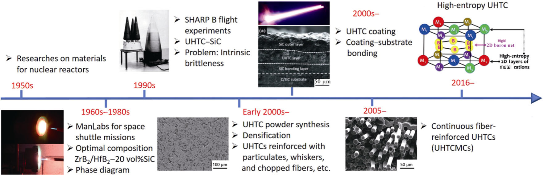
Particle toughening is a classical and widely applied method for enhancing the fracture toughness of ceramic materials by incorporating hard particles into the ceramic matrix to impede crack propagation. The primary toughening mechanisms include crack deflection, crack branching, particle pull-out, and crack bridging. As a crack propagates through the matrix, it encounters hard particles, causing the crack path to deflect or branch, thereby increasing the energy required for crack extension. Additionally, when the interfacial bonding strength between the particles and the matrix is relatively low, the crack propagates along the interface, resulting in particle pull-out, which further dissipates energy and improves toughness [45-46]. For example, introducing 20 vol% SiC particles into ZrB2 matrix resulted in an increased fracture toughness of up to 7.8 MPa·m1/2 and a bending strength of up to 549.8 MPa [47], highlighting significant toughening effects.
3.2 Soft-phase toughening
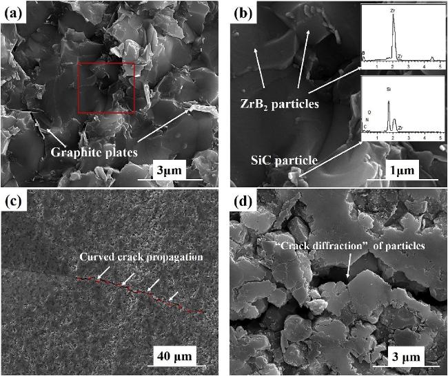
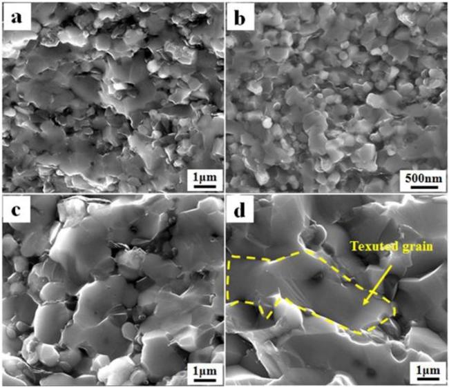
Soft-phase toughening enhances the toughness of ceramic materials by introducing low-hardness, low-elastic-modulus soft phases into the ceramic matrix to impede crack propagation. The primary toughening mechanisms include crack blunting and plastic deformation. During crack propagation, when the crack tip encounters a soft phase, the crack is blunted, reducing stress concentration at the tip. Additionally, the plastic deformation of the soft phase absorbs part of the energy associated with crack propagation, delaying its progress and improving the material's toughness [48-49]. For example, Wang et al. [50] prepared graphite sheet toughened ZrC ceramics through hot pressing sintering process. The density of pure ZrC ceramics sintered was less than 83%, and the density of ZrC ceramics sintered at 1900-2000 °C with the addition of 8.94% graphite sheets was higher than 98.4%, with an increase of more than 15%. Based on the above idea, by adding graphite sheets to adjust the carbon zirconium molar ratio, when the C: Zr ratio is 2:1, the ceramic material has a relatively high density (98.4%) and good microstructure (grain size between 5-10 μm) (as shown in Fig.3). After adding graphite soft phase, the fracture toughness of the ceramic increased from 3.0 MPa·m1/2 to 4.7 MPa·m1/2.
3.3 Short-cut fiber toughening
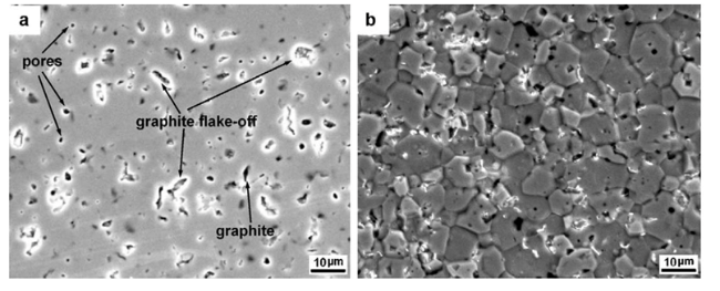
Short-cut fiber toughening is a method of improving material toughness by introducing short fibers to impede crack propagation. Commonly used reinforcing fibers include carbon fibers, SiC fibers, and oxide fibers [51]. The primary toughening mechanisms involve fiber pull-out, crack deflection, and fiber bridging. When a crack encounters short fibers, its propagation path is deflected, increasing the crack path length and the energy required for further extension. Additionally, the pull-out and bridging of fibers effectively absorb the energy of crack propagation, significantly enhancing the fracture toughness of the material [52-53]. For instance, Hu et al. [54] used pyro-carbon (PyC) coated short cut carbon fibers to toughen ZrC-SiC, tackling the dilemma between toughness and strength. With the uniform introduction of PyC coated carbon fibers into the ZrC-SiC, the crack propagation was changed into an obviously impeded one with more deflecting and flexuous path compared with uncoated composite (as shown in Fig.4). The fracture toughness of PyC-Cf/ZrC-SiC arrived at 7.27 ± 0.13 MPa·m1/2, 56% and 115% higher than that of Cf/ZrC-SiC and ZrC-SiC, with a rivaling flexural strength at 238 ± 16 MPa.
3.4 Continuous fiber toughening
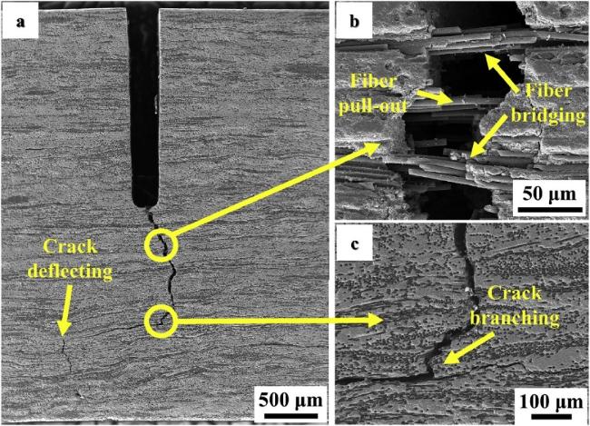
Continuous fiber toughening involves introducing continuous fibers, such as carbon fibers or SiC fibers, into a ceramic matrix to form continuous fiber-reinforced UHTC composites (Cf-UHTC or SiCf-UHTC). The primary toughening mechanisms include crack bridging, fiber pull-out, fiber fracture, and interfacial debonding. As cracks propagate, continuous fibers span the cracks and form bridges, preventing further crack extension. Additionally, the processes of fiber pull-out and fracture absorb significant energy, slowing crack propagation, while interfacial debonding between fibers and the matrix dissipates further energy, enhancing the material’s toughness [55-56]. In a study by Zhang et al. [57], Cf-ZrB2-SiC composites were fabricated using two-dimensional carbon fibers and nano-ZrB₂. These composites demonstrated excellent mechanical properties and non-brittle fracture behavior, with a fracture energy of 1338 J/m², an order of magnitude higher than that of traditional ZrB2-SiC ceramics. This improvement was attributed to combined toughening mechanisms, including crack deflection, fiber bridging, fiber pull-out, and crack branching (as shown in Fig. 5).
3.5 Design and selection of interface layer
The interface between fibers and the ceramic matrix is one of the critical factors determining the mechanical properties of ultra-high-temperature ceramic composites. The optimized design of the interface layer not only affects the interfacial bonding strength but also significantly influences the toughening effect of the composite. Therefore, optimizing for the interface layer is crucial for improving the overall performance of carbon fiber-reinforced UHTCs [58⇓-60].
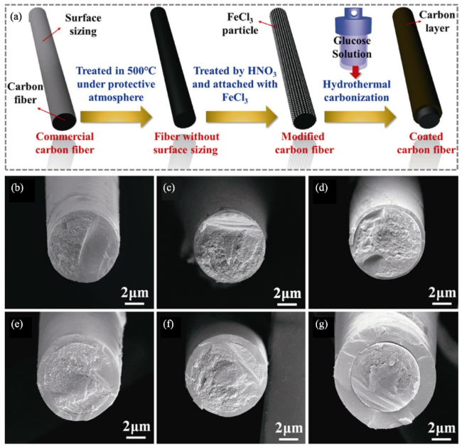
The carbon interface layer is typically formed on the surface of carbon fibers through chemical vapor deposition (CVD). Cheng et al. [61] constructed a nanocarbon interface on the carbon fiber surface using CVD, which effectively inhibited grain erosion and surface erosion. The 3D Cf/ZrC-SiC composite with a PyC interface maintained structural integrity after 300 seconds of ablation at 1800 °C and withstood thermal shock from rapid heating and cooling. Innovatively, Fang [62] et al. rapidly converted glucose into 5-hydroxymethylfurfural with the assistance of FeCl3, followed by transformation into a carbonaceous structure to form a hydrothermal carbon coating (as shown in Fig. 6). By adjusting the concentration of glucose, the thickness of the hydrothermal carbon coating can be effectively controlled to meet the requirements of various applications. The glucose-to-carbon conversion method offers advantages such as being environmentally friendly, cost-effective, and efficient, while avoiding fiber damage associated with traditional CVD processes. This ensures enhanced interfacial strength for toughened carbon fiber-reinforced composites.
Compared to PyC, boron nitride (BN) exhibits significantly superior oxidation resistance. Previous work [63] revealed that carbon begins oxidizing at 450 °C, whereas BN withstands oxidation up to 850 °C. Additionally, during oxidation, BN forms viscous liquid B2O3 at high temperatures, which provides self-healing capabilities by sealing cracks and effectively preventing oxygen penetration into the fibers. In high-temperature oxidative atmospheres and harsh environments, BN effectively protects fibers from oxidation or corrosive gases, significantly enhancing the high-temperature strength and creep resistance of the composites.
The SiC interface layer, known for its excellent chemical stability and high-temperature oxidation resistance, also plays a critical role. A previous study [64] demonstrated that the SiC interface layer exhibits strong bonding strength. However, this strong interfacial bonding suppresses mechanisms such as debonding, crack deflection, and fiber pull-out, leading to a slight reduction in fracture toughness. For example, Hu et al. [65] introduced a SiC interface phase into C/ZrC composites using PCS precursors (as shown in Fig. 7). This interface effectively protected carbon fibers from carbothermal reduction erosion and significantly improved the composite's ablation resistance. After one PIP cycle, the C/ZrC composite achieved a mass ablation rate of 0.0079 g/s and a linear ablation rate of 0.0084 mm/s.

To optimize the strength, toughness, and oxidation resistance of composites, multilayer interface designs have been widely utilized. These designs combine the advantages of various materials to enhance overall composite performance. A typical case is that Fang et al. [66] prepared PyC/SiC and PyC/BN interface-modified C/C-SiC-ZrC composites using chemical vapor infiltration (CVI) and PIP methods and evaluated the effects of different interface layers on mechanical and ablation properties. The results indicated that PyC/SiC-CSZ had slightly higher strength than PyC/BN-CSZ, with flexural strengths of 229.2 MPa and 214.9 MPa, respectively. However, PyC/BN-CSZ exhibited inferior ablation performance due to the vaporization of B2O3, which compromised the integrity of the oxidation film, allowing O2 to penetrate the BN interface layer and resulting in oxidative erosion of the carbon fibers.
4 Preparation methods of UHTCs and their composites
4.1 Hot pressing sintering and its derivative techniques
As the application of UHTCs in extreme environments continues to expand, research on their preparation methods has become increasingly important. Pressure assist sintering methods including hot press sintering (HP) and its various derivative processes, such as spark plasma sintering (SPS), reaction hot press sintering (RHP), as well as pressureless methods such as sintering (PLS), nano infiltration and transient eutectic (NITE), and ultrafast flash sintering (UHS), offer diverse approaches for fabricating high-performance UHTCs. This paper systematically introduces principles and applications of these sintering methods in the preparation of UHTCs and their composites.
4.1.1 Hot pressing sintering technology, HP
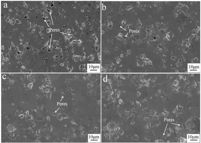
Hot pressing sintering (HP) is a traditional and widely used ceramic fabrication technique that densifies ceramic powders under high temperature and high pressure. Its principle involves simultaneously applying heat and pressure to promote particle contact and diffusion, thereby reducing porosity and forming a dense ceramic structure [67-68]. For instance, Gui et al. [69] used nanoscale ZrB2 powder as raw material and prepared ZrB2-SiC ceramics by single-step hot pressing at 1500-1800 °C and two-step hot pressing optimized at 1500 °C (as shown in Fig. 8). Fully dense ZrB2-SiC was obtained by single step hot pressing at 1800 °C, with a bending strength of 1044 ± 120 MPa and a fracture toughness of 6.21 ± 0.30 MPa·m1/2. An optimized two-step hot pressing process was designed based on densification curves to prepare ZrB2-SiC ceramics at low temperatures, resulting in improved bending strength (901 ± 109 MPa) and fracture toughness (6.07 ± 0.22 MPa·m1/2).
4.1.2 Spark plasma sintering technology, SPS
Spark plasma sintering (SPS) is a rapid sintering technique that uses pulsed electric current passing directly through ceramic powders to generate instantaneous high temperatures and plasma, enabling the rapid densification of powders [70-71]. For example, Yang et al. [72] successfully fabricated nearly fully dense HfB2 ceramics without additives using SPS (as shown in Fig. 9). At a sintering temperature of 1950 °C, the HfB2 ceramics exhibited optimal mechanical properties, with a hardness of 26.34 ± 2.1 GPa, a fracture toughness of 7.12 ± 1.33 MPa·m1/2, and a flexural strength of 501 ± 120 MPa. Mao et al. [73] prepared ZrB2-SiC-ZrC powders via the sol-gel method and sintered them using SPS at 2000 °C under 40 MPa, achieving materials with a relative density of 98%. After an ablation test at 2000 °C for 200 seconds, the material exhibited a linear ablation rate of -8.32×10⁻³ mm/s and a mass ablation rate of -4.268×10⁻⁴ g/s. Fine ZrO2 particles were uniformly distributed within the SiO2 melt, increasing the melt’s viscosity and acting as pinning agents, which enhanced the oxygen barrier of oxidation layer and resistance to mechanical erosion.
4.1.3 Reactive hot pressing, RHP
Reactive Hot Pressing (RHP) combines the advantages of hot pressing and in-situ reactions, achieving simultaneous material sintering and chemical synthesis by introducing chemical reactions during the hot-pressing process [74⇓-76]. Dense Ta0.2Hf0.8C-SiC (THS) ceramics were successfully prepared by Ni et al. [77] via RHP using the in-situ reaction of Ta0.2Hf0.8C (THC) with a small amount of Si (as shown in Fig. 10). A relativity density above 99% is achieved for the THS ceramics at a temperature as low as 1700°C. The improvement of densification of the THC ceramics can be mainly attributed to the formation of an instantaneous liquid phase and improved elements diffusion in THC lattice due to the formation of C vacancy. Due to the high densification level and uniform small grain size, the THS ceramics present excellent mechanical properties, with bending strength and fracture toughness as high as ∼637 MPa and 6.7 MPa m1/2, respectively.
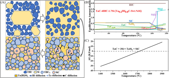
Fig. 10. (A) Schematic diagram showing phase and microstructure evolution mechanisms of THS during reactive hot-pressing, (B) thermodynamic equilibrium products of TaC-4HfC-1.7Si reaction system, and (C) standard Gibbs free energy at different temperatures. Reproduced with permission from Ref. [77], © The American Ceramic Society 2023. |
4.1.4 Pressureless sintering, PLS
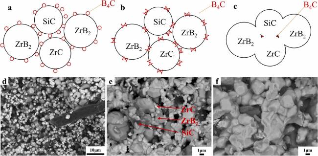
Pressureless sintering (PLS) is a traditional ceramic sintering method that densifies ceramic powders through diffusion mechanisms at high temperatures over extended periods, without applying external pressure [78⇓⇓-81]. Mao et al. [82] successfully fabricated PyC-Csf/ZrB2-SiC-ZrC ceramics with a homogeneous structure using cold isostatic pressing and pressureless sintering, and investigated their sintering mechanisms (as shown in Fig. 11). The addition of B4C improved the material's densification by removing oxide impurities and inhibiting grain growth. The long-term ablation behavior and mechanisms of PyC-Csf/ZrB2-SiC-ZrC ceramics were examined through oxyacetylene ablation tests. All samples exhibited excellent oxidation resistance and ablation performance. After 120 seconds of ablation at 2000 °C, the linear ablation rate and mass ablation rate of were approximately −4.68 × 10⁻³ mm/s and −9.17 × 10⁻⁴ g/s, respectively.
4.1.5 Nano-infiltration and transient eutectoid, NITE
The Nano-infiltration and transient eutectic (NITE) process is an innovative ceramic fabrication method that densifies porous matrices by infiltrating them with nanoparticles and achieving densification through eutectic reactions at high temperatures [83⇓-85]. For example, Chen et al. [86] prepared continuous SiC fiber-reinforced SiC matrix (SiCf/SiC) composites using the NITE method and investigated the residual stress in the composites using high-temperature Raman spectroscopy. As the temperature increased from room temperature to 1400 °C, the compressive residual stress in the matrix and fibers decreased from 1.29 to 0.62 GPa and 0.84 to 0.55 GPa, respectively, while the tensile residual stress at the interface decreased from 0.16 to 0.10 GPa. These changes in residual stress had little effect on the tensile strength of the composites but caused a slight reduction in tensile strain. The reduction in interfacial residual stress inhibited fiber/matrix debonding and fiber pull-out, which were responsible for the decrease in tensile strain.
4.1.6 Ultrafast high-temperature sintering, UHS
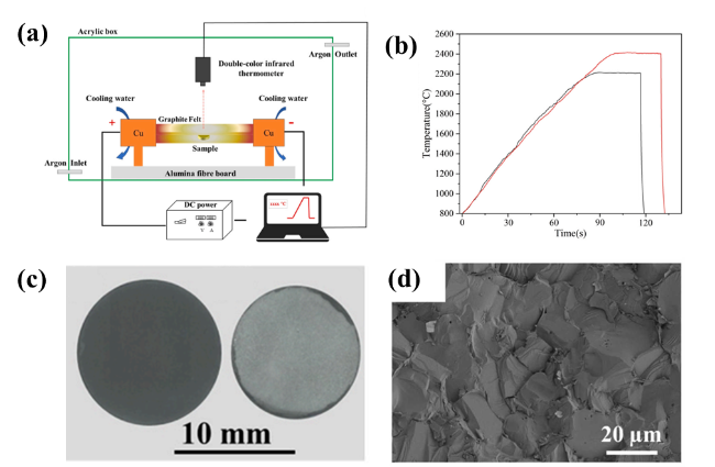
Ultrafast high-temperature sintering (UHS) is a cutting-edge ceramic sintering technology that achieves rapid densification by applying high temperatures in an extremely short timeframe [87⇓⇓-90]. Chen et al. [91] used UHS to fabricate ZrC ceramics with the addition of B4C. The ZrC ceramic with 2.5 wt% B4C achieved a density of 99.8% after sintering at 2300 °C for 120 seconds (as shown in Fig. 12). Compared to traditional pressureless sintering, which requires 60 minutes at 2400 °C, the ZrC ceramic containing 2.5 wt% B4C prepared using UHS at 2400 °C for 30 seconds exhibited higher relative density, smaller grain size, and higher Vickers hardness due to its faster heating rate and shorter sintering duration.
In recent years, significant progress has been made in the hot press sintering techniques used for fabricating UHTCs and their composites. From traditional hot press sintering to advanced methods such as spark plasma sintering, reactive hot pressing, pressureless sintering, nano-infiltration transient eutectic, and ultrafast high-temperature sintering, each approach offers unique advantages and specific applications. As technologies continue to advance, the combination and optimization of these sintering processes will provide more flexible and efficient solutions for the fabrication of high-performance UHTCs and composites.
Future research is likely to focus on the precise control of process parameters, further improvements in equipment, and the integration of different sintering techniques to meet the demands of UHTCs in increasingly harsh and extreme environments. Through continuous innovation and optimization, the fabrication technologies for UHTCs and their composites will offer more reliable material solutions for critical fields such as aerospace, defense, and energy.
4.2 Slurry Infiltration, SI
4.2.1 The principles of the slurry infiltration fabrication method
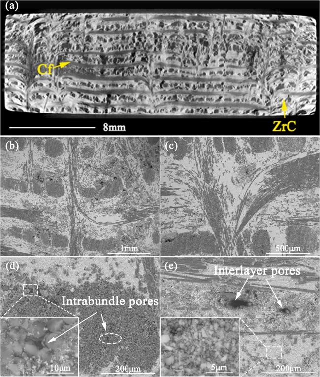
The slurry infiltration (SI) method is a common and effective process for fabricating fiber-reinforced UHTC composites. SI method involves mixing UHTC powders with aqueous or organic solutions to form a suspension, which is then introduced into fiber preforms through pressureless or pressurized infiltration methods [92,93]. This method is commonly used to introduce UHTC powders into structurally simple 2D fiber preforms [94,95]. Peng et al. [92] conducted the impregnation of a C/C preform using a low-viscosity ZrC slurry and investigated the impregnation effect through X-ray micro-CT and SEM analysis. The results demonstrated that the ZrC slurry was evenly distributed within the preform with a thickness of approximately 10 mm. ZrC particles effectively filled inter-bundle pores and large openings, though a small amount of residual pores remained within the micropores of the short-cut fiber webs. SEM images revealed that the ZrC slurry preferentially filled larger openings and inter-bundle pores, but had difficulty penetrating intrabundle micropores (as shown in Fig. 13). Additionally, small interlayer pores were observed, attributed to bubbles in the slurry and high local fiber density. The ZrC particles exhibited a lapped configuration without forming any physical or chemical bonds, and the gaps between particles required further filling in subsequent processes. Benefiting from the excellent impregnation effect of the SI process, the prepared C/C-ZrC preform achieved a density of 2.10 g/cm3.
4.2.2 Advantages and disadvantage of the slurry infiltration fabrication method
Slurry infiltration ensures the uniform distribution of ceramic matrix material within fiber preforms, significantly enhancing the overall uniformity and mechanical properties of the composite. It is compatible with various fiber types and ceramic matrix materials, allowing the flexibility to adjust slurry composition and process parameters to meet specific performance requirements. However, the interfacial bonding strength between the fibers and the ceramic matrix is a key factor in determining the mechanical properties of the material. Defects such as pores or insufficiently filled areas can easily occur during the slurry infiltration process, compromising the quality of the interfacial bonding.
4.2.3 Future development directions of the slurry infiltration fabrication method
By optimizing slurry formulations and particle distribution, the permeability and uniform distribution of the ceramic matrix within fiber preforms can be improved, enhancing material performance. Developing novel interfacial binders or surface treatment technologies can strengthen the interfacial bonding between fibers and the ceramic matrix, improving the mechanical properties of the materials. Incorporating advanced manufacturing technologies and intelligent control systems can enable precise control of the slurry infiltration process, increasing production efficiency and material consistency. Through continuous optimization of the slurry infiltration process, fiber-reinforced UHTC composites will demonstrate significant potential and value in a broader range of high-temperature applications.
4.3 Precursor infiltration and pyrolysis method, PIP
4.3.1 The basic principles of the PIP method
The basic principle of the PIP method involves impregnating a ceramic precursor solution into a fiber preform, followed by high-temperature pyrolysis to convert the precursor into ceramic matrix material. The fabrication process includes preparing the fiber preform, preparing the precursor solution, impregnation, pyrolysis, and final heat treatment. By repeating the impregnation and pyrolysis cycles multiple times, the pores in the fiber preform are gradually filled, resulting in a dense composite structure.
Common precursors include polycarbosilane, polyborosilazane, and polysiloxane, which undergo pyrolysis at high temperatures to form ceramic matrixes such as SiC, SiBCN, or SiO2 [11⇓⇓⇓⇓⇓⇓⇓⇓⇓⇓⇓⇓⇓⇓⇓⇓⇓⇓⇓⇓⇓⇓⇓⇓⇓⇓⇓⇓⇓⇓⇓⇓⇓⇓⇓⇓⇓⇓⇓⇓⇓⇓⇓⇓⇓⇓⇓⇓⇓⇓⇓⇓⇓⇓⇓⇓⇓⇓⇓⇓⇓⇓⇓⇓⇓⇓⇓⇓⇓⇓⇓⇓⇓⇓⇓⇓⇓⇓⇓⇓⇓⇓⇓⇓⇓⇓⇓⇓⇓⇓⇓⇓-104]. The selection and preparation of the precursor solution are critical to the PIP method, directly influencing the composition and properties of the final composite. A typical example is that Yan et al. [105] combined a novel HfC precursor with a PCS precursor using precursor infiltration and pyrolysis to fabricate 3-dimensional 4-directional (3D4d) Cf/HfC-SiC composites. The HfC precursor, known for its high stability and ease of handling, has been proven highly suitable for the PIP process. The 3D4d Cf/HfC-SiC composite, with a maximum SiC/HfC ratio of 22.5/11.8, exhibited a high flexural strength of 386.2 ± 50.0 MPa and a fracture toughness of 15.9 ± 0.1 MPa·m1/2. Furthermore, the intercrossed microstructure of the HfC and SiC matrices ensured uniformity, benefiting both the mechanical and ablation properties of the material.
Fiber preforms are impregnated with precursor solutions under vacuum or pressurized conditions to ensure the precursor uniformly penetrates the pores between fibers. After impregnation, the preforms undergo a drying process to remove the solvent and excess precursor solution. Previous works have shown that higher impregnation pressures improve precursor permeability, thereby increasing the final material density. For example, Cheng et al. [106] developed a novel SiHfBOC precursor and used high-pressure-assisted infiltration and pyrolysis to fabricate PyC-Cf/SiHfBOC composites. After only nine impregnation-pyrolysis cycles, the composites achieved a relative density exceeding 90% (as shown in Fig. 14). Under the modification effect of Hf, the composite formed an in-situ dense HfO2-SiO2 protective layer on its surface after ablation at 1800 °C, effectively preventing high-temperature oxidative gases from further penetrating into the composite's interior.
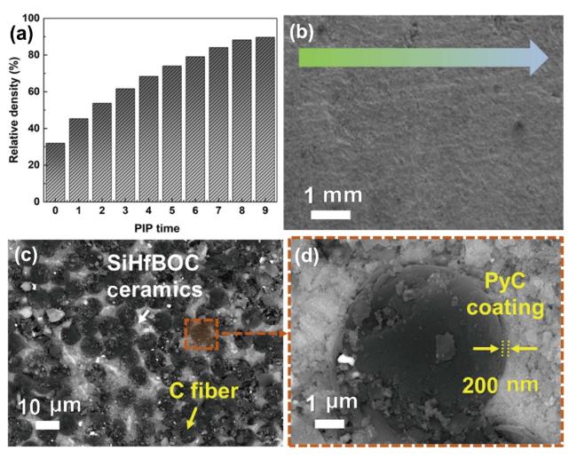
Fig. 14. (a) Density curve of 3D PyC-Cf/SiHfBOC composites with PIP process time, (b) SEM image of 3D PyC-Cf/SiHfBOC composites after 9 PIP process time, (c) BSE image of 3D PyC-Cf/SiHfBOC composites, and (d) high magnification micromorphology of (c). Reproduced with permission from Ref. [101], ©The Author(s) 2023. |
Under high-temperature conditions, the precursor undergoes pyrolysis, transforming into a ceramic matrix. This process involves volume shrinkage and crack formation, necessitating multiple cycles of impregnation and pyrolysis to gradually fill the pores and reduce crack generation. Final heat treatment further enhances the composite's densification and mechanical properties. After nine impregnation-pyrolysis cycles, the density of a carbon fiber-reinforced SiC composite increased to 2.13 g/cm3, with an open porosity of only 6.3%. The flexural strength reached 535.3 MPa, and the fracture toughness was as high as 16.8 MPa·m1/2 [107].
4.3.2 Advantages and disadvantages of the PIP method
The PIP method offers advantages such as a relatively simple process, lower costs, and suitability for fabricating components with complex shapes. Additionally, it allows for control over the microstructure and properties of the final composites by adjusting the type of precursor and the number of impregnation-pyrolysis cycles. However, the PIP method also faces challenges, including volume shrinkage and crack formation during pyrolysis, a longer processing cycle, and difficulties in achieving full densification. These issues limit its application in large-scale industrial production. To address these challenges, further optimization of process parameters and the development of novel precursor materials are necessary.
4.3.3 Recent advancements in the PIP method
Researchers are focused on developing precursor materials with lower pyrolysis temperatures, reduced volume shrinkage, and higher ceramic yields. For example, Huang et al. synthesized a novel SiC precursor by mixing boron-containing phenolic resin with hydrolyzed tetraethyl orthosilicate and fabricated ablation-resistant C/C-SiC composites. The results showed that during the precursor’s pyrolysis process, the carbon phase was uniformly surrounded by a silica phase, facilitating the carbothermal reaction. After heating at 1600 °C, the precursor fully transformed into SiC. The SiC shell completely encapsulated the carbon, with some ceramics exhibiting carbon cores. During ablation, the carbon core hindered the flow of molten silica, helping to prevent oxygen infiltration and resist flame erosion [108].
The structural design of the fiber-ceramic matrix interface is critical for improving the mechanical properties of composites. By coating the fiber surface with an interfacial layer or modifying the chemical properties of the fiber surface, the toughening effect and oxidation resistance of the material can be significantly enhanced. Cheng et al. [109] fabricated C/C-SiC-ZrC and C/C-SiC composites with an isothermal chemical vapor infiltration (ICVI)-SiC interphase using the electromagnetic coupling chemical vapor infiltration (ECVI) and PIP processes. The C/C-SiC composite with the ICVI-SiC interphase exhibited the highest flexural strength of 306.5 MPa. The C/C-SiC-ZrC composite with the ICVI-SiC interphase showed the lowest linear ablation rate (0.37 μm/s) and mass ablation rate (0.04 mg/cm2·s) after 500 seconds of ablation under an oxy-acetylene flame.
Although the PIP method is a key technology for fabricating fiber-reinforced UHTC composites and holds great potential for broad applications, this process still faces several challenges that require further research and optimization. In the future, with the development of novel precursor materials, optimization of the pyrolysis process, and precise design of composite interfacial structures, the PIP method is expected to play a significant role in a wider range of industrial applications.
4.4 Reactive melt infiltration technology, RMI
4.4.1 The basic principle of the RMI method
Reactive melt infiltration (RMI) is an effective method for fabricating ultra-high temperature ceramic matrix composites. It involves infiltrating liquid metal or alloy melts into a fiber preform at high temperatures, where they undergo a chemical reaction to form a dense ceramic matrix, thereby enhancing and toughening the material. The basic principle of RMI is to utilize the high-temperature fluidity of liquid metal or alloy. Through capillary action, the melt is infiltrated into the fiber preform, where it reacts with the chemical components within the preform to form a ceramic matrix. The RMI method typically involves the following steps: preparation of the fiber preform, selection of the melt material, and the infiltration process [110⇓⇓⇓⇓⇓-116].
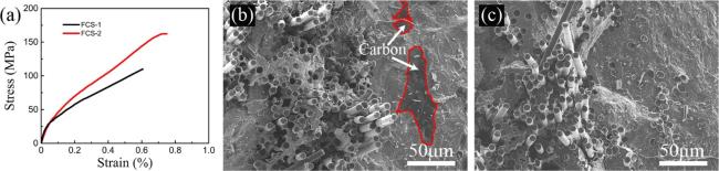
Fiber preforms are typically composed of carbon fibers, silicon carbide fibers, or oxide fibers, and are fabricated using methods such as weaving, layering, or hot pressing. The structural design and porosity control of the fiber preform are critical for the subsequent infiltration process. For instance, Zhang et al. [117] prepared a novel porous carbon structure within the carbon fiber weave using phenolic resin and a pore-forming agent, creating openings accessible to liquid silicon. After optimizing the pore structure, the C/SiC composite matrix prepared using RMI showed no detectable large residual carbon or silicon. The tensile strength of the composite reached 159 MPa, representing a 46% improvement compared to composites without the pore-forming agent (as shown in Fig. 15).
Common melt materials include silicon, aluminum, titanium, and their alloys, with the specific choice depending on the desired type of ceramic matrix. Ye et al. [118] used a Si-Zr alloy as the melt to fabricate gradient-structured Cf/SiC-ZrC composites via RMI technology. The ZrC-SiC gradient structure on the composite surface exhibited excellent ablation resistance and impact performance, while the high-SiC-content core provided good strength retention. This unique matrix structure design was achieved through the combination of a single-level porous structure with highly graphitized porous carbon and the uniquely formulated Si-Zr alloy. The composite's flexural strength after ablation reached 166 ± 4.4 MPa, significantly surpassing that of similar Cf/SiC-ZrC composites reported in the literature.
4.4.2 Advantages and disadvantages of the RMI method
The RMI method offers advantages such as high efficiency, short preparation cycles, and suitability for fabricating large-sized and complex-shaped products. Additionally, by controlling the melt composition and reaction conditions, the RMI method allows flexible adjustment of the composite's microstructure and final properties. However, it also presents certain challenges, such as the potential formation of pores during the infiltration process and uneven material interfacial reactions, which may affect the mechanical properties and durability of the final material.
4.4.3 Recent advancements in the RMI method
By optimizing infiltration temperature, pressure, and time, researchers have successfully reduced pore formation during the infiltration process and increased the material's density. Ni et al [119] infiltrated silicon into porous Cf/HfC-C preforms prepared using the sol-gel process to fabricate and optimize 3D-Cf/HfC-SiC-based composites. The fibers and interfacial phases of the composites were found to undergo erosion, which was further exacerbated during the RMI process, resulting in the formation of hafnium-containing substances on the fiber surfaces. The degradation of fibers and interfacial phases was primarily caused by the reaction between HfO2 and the C/SiC interfacial layer at high temperatures. To address this issue, a two-step carbothermal reduction treatment method was proposed to optimize the preparation process. As a result, fiber/interfacial erosion was reduced (as shown in Fig.16), and the mechanical properties of the composites were improved. The flexural strength increased by approximately 49%, from 214.1 ± 15.7 MPa to 319.0 ± 26.0 MPa.
As we have mentioned before, the interfacial structure between fibers and the ceramic matrix plays a critical role in determining the performance of composites. By coating the fiber surfaces with interfacial layers (e.g., carbon layers or nitride layers), interfacial reactions can be effectively controlled, preventing the formation of brittle phases and thereby enhancing the toughness of the composites. A typical example is demonstrated by Dong et al. [120], who used an improved RMI method to infiltrate silicon into nano-porous Cf/ZrC-C preforms, resulting in Cf/ZrC-SiC composites with a density of 2.52 g/cm³, a porosity of 1.68%, and excellent mechanical properties. The dense Cf/ZrC-SiC composites, free of noticeable bulk Si/C residues and fiber/interfacial phase degradation, were achieved due to the ZrC "protective coating" surrounding the carbon fibers within the porous Cf/ZrC-C preform. The composite exhibited a flexural strength of 380 MPa and an elastic modulus of 61 GPa, significantly surpassing those of Cf/ZrC-SiC composites prepared by traditional RMI methods.
To address the performance of composites prepared by the RMI method under extremely high-temperature environments, various enhancement methods, such as introducing ultra-high temperature ceramic phases, nanoparticle reinforcement, and composite interfacial layer design, to improve oxidation resistance and high-temperature mechanical properties, have been developed. Fu et al. [121] utilized ZrB2 vacuum infiltration combined with reactive melt infiltration to fabricate C/C-ZrB2-ZrC-SiC composites with higher ceramic phase content and a more uniform distribution. Compared to C/C-ZrC-SiC composites, the C/C-ZrB2-ZrC-SiC composites exhibited a 68.9% lower mass ablation rate and a 29.7% lower linear ablation rate. The improvement in ablation performance was attributed to the volatilization of B2O3, which dissipated part of the heat, and the formation of a continuous ZrO2-SiO2 protective layer from the uniformly distributed ZrO2. This layer effectively blocked oxygen infiltration and reduced ablation.
RMI is an efficient technique for fabricating fiber-reinforced UHTC composites, with broad application prospects. However, the RMI process still faces numerous challenges, such as pore control and the uniformity of interfacial reactions, requiring further research and optimization. In the future, with the development of novel melt materials, optimization of infiltration processes, and precise design of interfacial structures, the RMI method is expected to play a crucial role in a wider range of industrial applications, particularly in the fields of aerospace, nuclear industries, and structural materials for extreme environments.
4.5 "Solid-Liquid" combination process
Traditional densification processes for composites, such as hot-press sintering, reactive melt infiltration, and chemical vapor infiltration, often achieve high densification at the cost of damaging the reinforcing fibers, which negatively impacts the overall performance of the composites. To address this issue, Hu et al. [122] proposed an innovative "Solid-Liquid" combination process. This method combines solid-phase and liquid-phase fabrication techniques to achieve efficient densification of UHTC composites while effectively protecting the reinforcing fibers (as shown in Fig. 17).
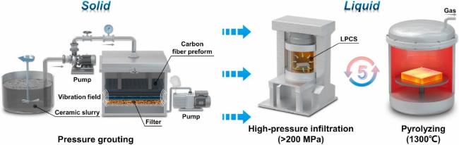
4.5.1 Solid phase: Ultra-high temperature ceramic vibration-assisted slip casting
The solid-phase preparation method employs vibration-assisted slip casting to directly introduce ultra-high temperature ceramic powder particles into continuous fiber reinforcements. Through the action of vibration, ceramic powders are uniformly distributed within the pores of the fiber preform, enabling the incorporation of ceramic powder exceeding 30 vol%. Traditional ceramic powder introduction techniques are often limited by the size and shape of the fiber preform. In contrast, vibration-assisted slip casting utilizes physical vibration to uniformly distribute ceramic powders in fiber preforms of various complex shapes and sizes without constraints. This process also allows precise control of the ceramic component content and distribution by adjusting slip casting parameters, such as vibration frequency and slurry concentration. Experimental results show that the green body prepared using this method achieves a density exceeding 65%, providing a solid foundation for subsequent liquid-phase preparation processes [123].
4.5.2 Liquid phase: silicon carbide precursor high-pressure impregnation and low-temperature pressureless sintering
In the liquid-phase preparation method, one of the most important works is that Hu et al. [122] proposed a combined process of ultra-high-pressure impregnation and low-temperature pressureless sintering. First, a liquid ceramic precursor is impregnated into the solid-phase-treated green body under high pressure exceeding 200 MPa. This process ensures that the liquid precursor thoroughly infiltrates the fine pores within the green body, achieving internal densification of the material. In traditional processes, sintering temperatures typically exceed 1900 °C and are accompanied by high pressure, which can easily cause high-temperature damage to the carbon fiber reinforcement. However, in the "Solid-Liquid" combination process, the use of low-temperature pressureless sintering technology reduces the sintering temperature to 1300 °C, allowing the ceramic matrix to solidify and densify under low-temperature conditions. This process not only effectively protects the integrity of the carbon fiber reinforcement but also significantly reduces manufacturing costs and energy consumption [124]. The microstructure of the ZrB2-SiC ceramic matrix and interfaces between the matrix and carbon fibers were further characterized by transmission electron microscopy (TEM). Fig. 18a and c shows that the gaps between the micron-sized ZrB2 particles are completely filled with the pyrolytic SiC, and several nanoscale ZrB2 particles are also dispersed within the SiC matrix (indicated by red arrows in Fig. 18c). The direct bonding between ZrB2 and SiC can effectively enhance the strength of the ceramic matrix, transforming the originally loose and porous ZrB2 particles into a high-strength and dense ceramic matrix bonded by the amorphous−nanocrystalline SiC ceramic [122].
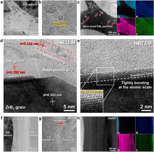
4.5.3 Research progress of "Solid-Liquid" combination process
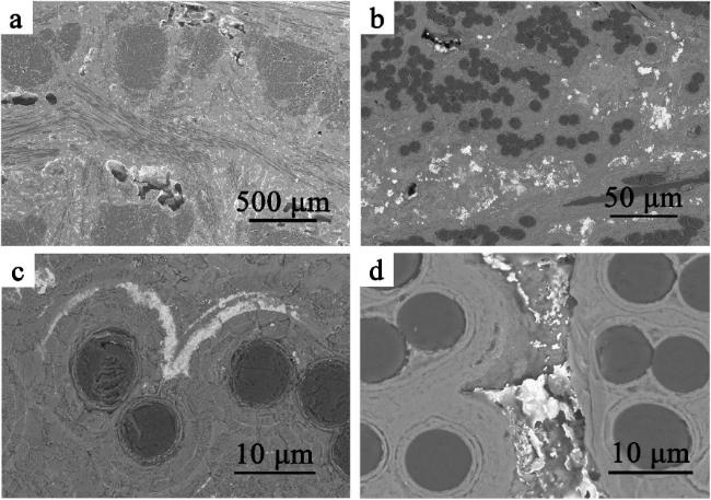
The research team led by Zhang [122,125-126] successfully fabricated Cf/ZrB2-SiC composites with highly uniform distribution by introducing nano-sized ZrB2 powders into three-dimensional needled carbon fiber weaves. It can be seen that the composite is near fully dense within the field of view, without visible defects such as cracks and pores. The pores and cracks in the green body are fully filled by the in-situ pyrolytic SiC (indicated by red arrows in Fig. 19 c and d). There are no obvious defects found in the composite, strongly proving that the high-pressure infiltration technology can effectively eliminate closed pores inside the composite. During the PIP cycles by high-pressure infiltration and low-temperature pyrolysis, the in-situ pyrolytic SiC not only fully fills the gaps between closely packed ZrB2 particles, but also tightly bonds the originally dispersed particles, resulting in a concurrent improvement in the relative density and matrix strength of the composite.
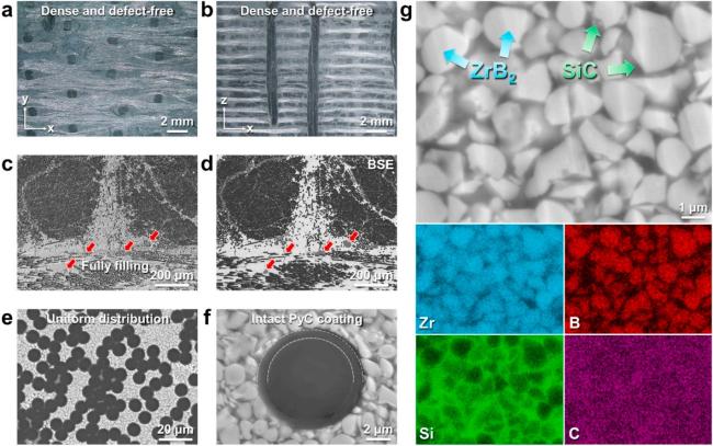
Fig. 19. Macro-and micro-structure of the as-prepared Cf/ZrB2-SiC composite: (a) and (b) surface and cross-section morphologies; (c) ∼ (f) SEM images of cross-section morphology at different magnifications; (g) elemental distribution of the matrix. Reproduced with permission from Ref. [122], © Elsevier 2024. |
To further enhance the performance of composites, Zhang et al. [124] applied "Solid-Liquid" combination process to fabricate Cf/ZrC-SiC composites based on the ZrC system. During the solid-phase stage, they utilized needled carbon fiber weaves as the matrix and introduced ZrC particles into the fiber preforms using a vibration-assisted slip casting technique, achieving a ceramic particle incorporation rate of over 45 vol%. Based on this foundation, the researchers introduced a SiC precursor into the green body and performed pressureless sintering at 1300 °C, resulting in highly densified Cf/ZrC-SiC composites. Microstructural analysis revealed that the sintered composites exhibited uniform and dense ceramic particle distribution in both inter-bundle and intra-bundle regions. Furthermore, ZrC and SiC ceramics were highly uniformly arranged and bonded within the carbon fiber weave. This composite not only exhibited excellent mechanical properties but also showed superior oxidation resistance, making it suitable for high-temperature structural component applications. The bending strength and fracture toughness of composite materials are 286 ± 25 MPa and 11.12 ± 1.25 MPa m1/2. A lot of fiber pull-outs, fiber bridging and broken carbon fibers appeared at the fracture site (as shown in Fig. 20), which released energy during the crack propagation process. It is precisely this multi-scale toughening mechanism that maintains the structural integrity of the SENB tested samples without catastrophic damage.
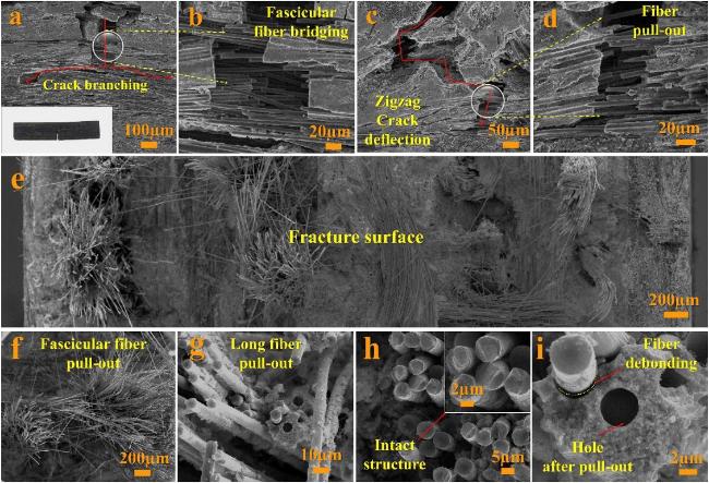
Fig. 20 The microstructures of specimen after mechanical property test: (a) crack branching; (b) fascicular fiber bridging; (c) crack deflection; (d) fiber pull-out; (e) the whole fracture surface morphology; (f) fascicular fiber pull-out; (g) long length fiber pull-out; (h) intact structure of carbon fiber; (i) fiber debonding and hole after pull-out. Reproduced with permission from Ref. [124], © Elsevier 2019. |
4.5.4 Advantages of "Solid-Liquid" combination process
The "Solid-Liquid" combination process demonstrates significant advantages over traditional densification techniques. Firstly, this process enables the densification of composites at lower temperatures, effectively preventing damage to reinforcing fibers, which is particularly critical for carbon fiber-reinforced ceramic composites. Secondly, the solid-phase slip casting technique ensures the uniform introduction of high-content ceramic powders into the fiber preform, overcoming the performance instability issues caused by uneven powder distribution in traditional methods. Additionally, the combination of ultra-high-pressure impregnation and low-temperature pressureless sintering simplifies the preparation process, shortens the production cycle, and reduces both energy consumption and costs.
4.5.5 Application prospects and future research directions
The successful application of the "Solid-Liquid" combination process offers a new perspective for further promoting ultra-high-temperature ceramic composites in the aerospace field. By optimizing slip casting parameters, impregnation pressure, and sintering conditions, the densification and overall performance of the materials can be further enhanced. Developing densification techniques suitable for large-scale and complex-shaped components and verifying their feasibility in practical applications is essential. Exploring a broader range of ceramic matrix materials and reinforcing fiber combinations will address the needs of various application scenarios. Additionally, conducting long-term high-temperature service tests will help assess the composites' stability and reliability, providing critical data support for their engineering applications.
As an emerging fabrication method for UHTC composites, the "Solid-Liquid" combination process has successfully overcome several challenges of traditional techniques, particularly in the incorporation of high-content UHTC and the protection of fiber reinforcements. Further development and optimization of this process will drive the widespread application of UHTC composites in aerospace and high-temperature structural components, which also offering valuable guidance for developing new materials for extreme high-temperature environments.
4.6 Additive manufacturing technology, AM
In recent years, additive manufacturing (AM) technology has emerged as a key research focus for the preparation of ceramic matrix composites due to its high flexibility, efficient material utilization, and capability to fabricate complex structural components. Additive manufacturing, also known as 3D printing, constructs three-dimensional structures through layer-by-layer material deposition, offering significant advantages in flexibility and precise control. Currently, the primary AM techniques used for ceramic matrix composite fabrication include stereolithography (SLA), selective laser sintering (SLS), fused deposition modeling (FDM), and direct energy deposition (DED), among others [127⇓⇓⇓-131].
Stereolithography (SLA) is an additive manufacturing technology that utilizes photopolymerization of photosensitive resins under exposure to laser or ultraviolet (UV) light of specific wavelengths. For ceramic matrix composites, SLA typically involves mixing ceramic powders with photosensitive resin, followed by layer-by-layer curing and stacking to form a composite material with a ceramic matrix. The advantages of this technique include high resolution and the ability to fabricate complex structures. However, it also faces challenges such as shrinkage and crack formation during fabrication [132⇓-134]. Shen et al [135] prepared a photocurable ceramic precursor slurry with a carbon fiber volume fraction of up to 25%. By combining SLA with PIP, Shen et al. successfully fabricated carbon fiber-reinforced SiC ceramic matrix composites. The volumetric density and flexural strength of the Cf/SiC composites reached 2.03 ± 0.04 g/cm3 and 109.99 ± 15.05 MPa, respectively, which provides a reference for the additive manufacturing of Cf/SiC composites using stereolithography.
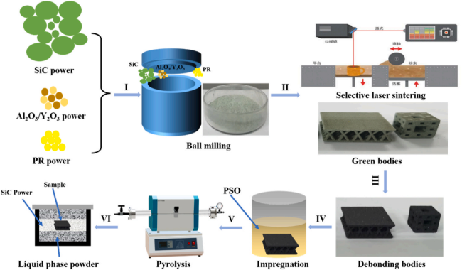
Selective laser sintering (SLS) uses a laser beam to selectively sinter or melt ceramic powders pre-deposited on a forming platform, constructing three-dimensional structures layer by layer. SLS is suitable for a wide range of ceramic materials and can achieve high material density. However, due to the high melting point and low thermal conductivity of ceramics, temperature gradients must be carefully controlled during the SLS process to prevent cracks caused by thermal stress [136⇓-138]. For example, Huang et al. [139] proposed an efficient technique combining selective laser printing with precursor infiltration and pyrolysis and liquid phase sintering for fabricating SiC ceramics. Using selective laser printing powders composed of SiC, Al2O3, Y2O3, and phenolic resin, green bodies with specific microstructures were obtained. After selective laser printing, precursor infiltration. pyrolysis, and pressureless sintering, the fabricated SiC ceramics (as shown in Fig. 21) achieved a bending strength of 150 MPa and a relative density of 98.2%.
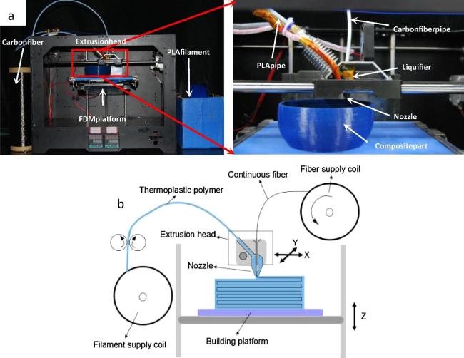
Fused deposition modeling (FDM) technology creates three-dimensional structures by depositing layers of ceramic matrix composite filaments, which are heated and melted during the process. The main advantages of FDM include low equipment costs and minimal material waste (as shown in Fig. 22). However, due to the high viscosity of the molten material, FDM faces limitations in manufacturing precision and material uniformity [139⇓⇓-142]. Cheng et al. [142] utilized a hydrothermal reaction to deposit sugar-derived carbon as an interface coating on continuous carbon fibers, resulting in flexible hydrothermal carbon-coated continuous carbon fibers suitable for 3D printing. Using FDM, continuous Cf/ZrB2-PCL filaments were printed to fabricate Cf/ZrB2-PCL green bodies with different fiber orientations. These green bodies were further densified through SiC precursor infiltration and pyrolysis. The resulting Cf/ZrB2-SiC composites achieved a bending strength of 218.1 ± 21.3 MPa and a fracture toughness of 9.40 ± 1.45 MPa·m1/2.
Additive manufacturing technologies enable the direct fabrication of complex geometries, which is particularly beneficial in applications such as thermal protection systems. The ability to produce complex structures significantly enhances the overall performance of materials. Using AM, different ceramic materials can be introduced into specific regions or even fabricated as gradient materials, thereby improving thermal shock resistance and mechanical properties. AM can also be combined with processes like reaction sintering and hot isostatic pressing to produce UHTC with high density and purity, further enhancing material performance.
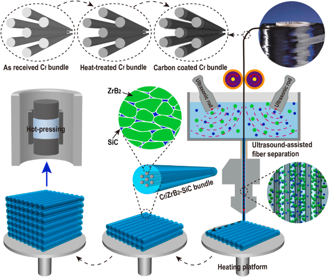
To date, notable progress and breakthroughs have been achieved in the additive manufacturing of carbon fiber-reinforced ceramic matrix composites [143]. Kemp et al. [144] utilized direct ink writing (DIW) technology with a composite ink consisting of ZrB2 powders, SiC precursors, and SiC short fibers. The printing was conducted at room temperature, followed by pyrolysis at 1200 °C to fabricate SiCf/ZrB2-SiC composites. However, as the fiber content increased, issues such as fiber misalignment and material cracking arose due to gas release and matrix shrinkage during polymer curing and pyrolysis. Additionally, the pyrolyzed components often exhibited defects, limiting their mechanical performance. Li et al. [145] addressed these issues by employing DIW combined with ultrasound-assisted fiber separation. During the direct ink writing of continuous carbon fiber/ceramic composites, ceramic slurry was impregnated into continuous carbon fiber bundles. A subsequent low-temperature hot-pressing process was used to enhance the robustness of the fabricated structures, indirectly resulting in Cf/ZrB₂-SiC ceramic matrix composites (as shown in Fig. 23).
Despite these advancements, several challenges remain in the additive manufacturing of UHTC, such as the high brittleness of materials leading to crack formation and the control of thermal stresses during the fabrication process. Future research should focus on optimizing process parameters, developing new material systems, and exploring the integration of multiple manufacturing techniques. AM offers a highly flexible and promising pathway for fabricating ceramic matrix composites, especially UHTC. While challenges persist, ongoing research and technological innovations are expected to position AM as a pivotal technique in the manufacturing of high-temperature materials, driving the widespread application of ceramic matrix composites in aerospace, defense, and other critical fields.
Different preparation methods exhibit unique characteristics and are applicable to various systems of UHTCs and their composites. The advantages, limitations, and future development directions of these methods have been summarized in Table 2. The development of preparation techniques for UHTCs and their composites provides critical material support for advanced technological equipment operating under extreme conditions, offering significant scientific research value and broad prospects for industrial applications.
Table 2 Advantages and Disadvantages of Various Fabrication Techniques for UHTCs and Their Composites |
| Method | Advantages | Disadvantages | Future development directions |
|---|---|---|---|
| HP | Simple process, suitable for large-scale production | Stress may be generated during the preparation process. Manufacturing UHTC composites with complex structures is challenging. | Developing new sintering methods and optimizing process parameters. |
| SI | Good compatibility, relatively flexible preparation process, and uniform distribution of ceramic matrix within the fibers | Prone to defects, affecting interfacial bond strength. The preparation cycle is relatively long. | Optimizing slurry formulations and particle distributions to improve the uniformity of matrix distribution, and developing new types of interfacial binders or surface treatment technologies. |
| PIP | Simple process, low cost, suitable for components with complex shapes | Volume shrinkage and cracking are easily induced during the pyrolysis process. The preparation cycle is lengthy, making it difficult to attain full densification. | Developing novel precursor materials, optimizing the pyrolysis process, and precisely designing the interface structure of composite materials. |
| RMI | High preparation efficiency, short cycle time, high densification, suitable for large and complex products | Fibers are susceptible to damage during the infiltration process. | Developing novel melt materials, optimizing the infiltration process, and precisely designing the interface structure. |
| "Solid-Liquid" combination process | Densifies composites at low temperatures, protecting fibers. Ensures even powder distribution for stable performance. | The process is relatively complex, requiring precise control of the solid-to-liquid phase ratio and reaction conditions. | Optimizing the process to enhance material densification and performance, and developing densification techniques suitable for large-scale and complex-shaped components, and validating their feasibility. |
| AM | Offers high flexibility and precision, enabling the manufacture of components with complex structures | Higher equipment costs. Potential for thermal stresses and cracks, which can affect the mechanical properties of the material. | Optimizing process parameters, developing new material systems, and exploring the integration of multiple manufacturing technologies. |
5. Anti-oxidation and ablation behavior and mechanism of UHTCs
In high-speed flight environments, the anti-oxidation stability of thermal protection materials is crucial. However, due to the extreme operating conditions, UHTCs face numerous challenges in practical applications. These challenges include unclear interaction mechanisms between the materials and their environment, as well as limitations in their oxidation resistance and ablation performance. These issues directly affect the reliability and aerodynamic performance of structural components in hypersonic vehicles. Therefore, in-depth studies on the oxidation behavior, mechanisms, and ablation resistance of UHTCs are critical for their application in high-temperature fields.
5.1 Progress in ablation testing methods
The oxidation resistance and ablation performance of UHTCs largely depend on the composition and microstructure of the surface oxide layer. At high temperatures, the material surface reacts with oxygen to form an oxide layer, which can provide some level of protection to the substrate material. However, current oxidation experiments are typically conducted at temperatures below 2000 °C due to limitations in laboratory equipment. In actual service conditions, the operating temperatures of UHTCs often exceed 2000 °C, and the materials are subjected to the intense erosion or oxidation effects of corrosive gases. This necessitates the development of more stringent experimental methods to accurately simulate the oxidation behavior of UHTCs under real-world conditions. To better simulate the ablation behavior of UHTCs in actual service environments, researchers have developed various advanced ablation testing methods. The characteristics of various ablation testing methods have been summarized in Table 3. These methods include oxy-acetylene flames, oxy-propane flames, plasma flames, and arc-jet wind tunnels. These facilities can provide extreme high-temperature and high-heat-flux conditions, realistically mimicking the environments UHTCs experience during hypersonic flight or atmospheric reentry [146⇓⇓-149].
| Method | Characteristics | Advantages | Disadvantages |
|---|---|---|---|
| Oxy-acetylene ablation | Uses oxy-acetylene flame flow as a heat source for ablation erosion, widely used. | Reliable and cost-effective, suitable for rapid screening of UHTCs materials. | Only simulates high-temperature oxidation environments, without considering plasma-material interaction. |
| Oxy-propane ablation | Uses oxy-propane flame flow as a heat source for ablation erosion. | More stable, safer, and lower in cost compared to oxy-acetylene flame. | Lower testing temperature than oxy-acetylene flame, and similarly, the simulated ablation environment is relatively single. |
| Plasma ablation | Forms a plasma beam by ionizing gas to generate high-temperature, high-speed flame impacting the material surface. | High temperature and high heat flux density, better simulating high heat flux environments; customizable heat flux for different ablation environments. | Relatively low plasma flame velocity; simulated environment differs from real-world conditions. |
| Arc-jet wind tunnels | Testing in a continuous open-circuit arc jet wind tunnel, simulating actual operating conditions with arc jet-generated high-temperature, high-speed airflow. | The simulated ablation environment is closer to real-world conditions, high reference value. | High testing costs, long cycles, and difficulty, unsuitable for initial screening. |
Taking arc-jet wind tunnel testing as an example, researchers conducted simulated ablation experiments on ZrB2-WC-SiC composites using simulated air and pure nitrogen at high enthalpy flows exceeding 20 MJ/kg. The test temperatures reached 2650 °C and 2800 °C. Samples tested under both conditions exhibited similar oxide structures. Samples exposed to air formed a silica-dominated glass layer on the surface, which reduced bubble rupture phenomena. In contrast, samples exposed to nitrogen exhibited more intense volatilization in the subsurface layer [156].
5.2 Oxidation behavior and mechanism of Zr-based UHTCs
ZrB2-based and ZrC-based UHTCs exhibit excellent oxidation and ablation resistance under extreme conditions, primarily due to the formation of a ZrO2 oxide layer on the material surface. By incorporating high volume fractions of ZrB2 and ZrC into the matrix, higher amounts of ZrO2 can form during use, significantly enhancing the material's oxidation and ablation resistance.
In plasma wind tunnel experiments simulating hypersonic atmospheric re-entry conditions, it was demonstrated that ZrB2-SiC composites withstood 540 seconds of ablation test. The study revealed that the oxidation rate at 1800 °C was 10-5 g/cm2·h, with an oxide layer thickness of approximately 30 μm. The addition of SiC facilitates the formation of glassy SiO2, which optimizes the material's ablation resistance [157]. However, excessive SiC content may reduce the ablation resistance at ultra-high temperatures, especially above 2000 °C [158]. For instance, in Cf/ZrB2-SiC composites, high-melting-point oxide grains (ZrO2 grains) precipitate, coarsen, and sinter from the glassy SiO2 phase through a quasi-liquid-phase-assisted mechanism, as described by the following reaction equation.
| SiC(s) + 1.5O2(g) → SiO2(l) + CO(g) | (1) |
|---|---|
| SiO2(l) + SiC (l) → SiO(s) + CO(g) | (2) |
| SiO2(g) + CO(g) → SiO(s) + CO2(g) | (3) |
| ZrB2(s)+ 2.5O2(g) → ZrO2(s) + B2O3(g) | (4) |
The phase transformation of ZrO₂ leads to the formation of cracks in the oxide layer, which reduces the ablation resistance of the composite as the ablation temperature increases. Zeng et al. [159] investigated the ablation performance of Cf/C-SiC-ZrC-TiC, Cf/C-SiC, and Cf/C-TiC materials by introducing TiC into Cf/C-SiC-ZrC composites. During ablation tests conducted at 2500 °C, Cf/C-SiC-ZrC-TiC composites formed a high-viscosity, low-volatility protective layer composed of Zr-TiC and SiC substances on the surface. When the glassy SiO2 evaporated, titanium-rich oxides precipitated from the glass phase, reconstructing a low-volatility protective layer that further resisted erosion in ultra-high temperature environments. Additionally, the precipitated zirconium-rich oxides increased the viscosity of the oxide layer, enhancing the material's resistance to ablation flame erosion (as shown in Fig. 24). As a result, Cf/C-SiC-ZrC-TiC composites exhibited superior ablation resistance compared to Cf/C-SiC and Cf/C-TiC materials.
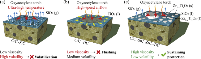
Fig. 25 Schematics of the ablation mechanisms of (a) C/C-SiC, (b) C/C-TiC, and (c) C/C-SiC-ZrC- TiC at 2500 °C. Reproduced with permission from Ref. [159], © Elsevier 2019. |
5.3 Oxidation behavior and mechanism of Hf-based UHTCs
HfB2-based and HfC-based UHTCs have garnered widespread attention due to their excellent ablation resistance. Compared to ZrB2-based and ZrC-based materials, the oxidation produced HfO2 from HfB2 and HfC exhibits a significantly higher melting point (2800 °C), enabling these materials to maintain good performance at even higher temperatures [160]. The ablation products of C/C-HfB2-SiC composites primarily consist of HfO2, SiO2, and B2O3. HfO2 and B2O3 are formed from the oxidation of HfB2, with HfO2 creating a dense oxide layer on the surface to prevent oxygen penetration. However, B2O3 in the matrix evaporates intensely due to the high ablation temperature and the severe erosion caused by the ablation flame, rendering it incapable of protecting the composite material. Some B2O3 may remain within the oxide layer or leave micropores during its escape due to incomplete evaporation or continued generation. The reaction is described by the following equation [161]:
| HfB2(s) + 2.5O2(g) → HfO2(s) + B2O3(g) | (5) |
|---|---|
| SiC(s) + 1.5O2 (g) → SiO2 (l) + CO(g) | (6) |
| SiO2 (l) → SiO2 (g) | (7) |
| SiC(s) + O2 (g) → SiO (l) + CO(g) | (8) |
| C(s) + 0.5O2 (g) → CO(g) | (9) |
| C(s) + O2 (g) → CO2(g) | (10) |
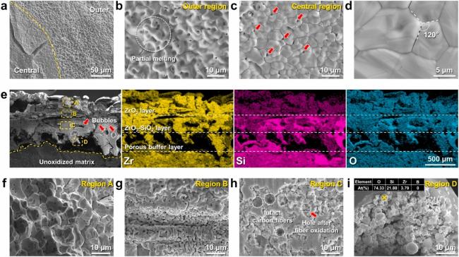
Via hot pressing sintering technology,Lyu et al. [162] fabricated HfB2-SiC composites. Remarkably, this composite demonstrates excellent non-ablative properties in an ultrahigh temperature oxygen-rich environment of 2500 °C with a linear ablation rate of only 2.5 × 10⁻⁴ mm/s. The formation of HfO2 and HfO2-SiO2 glass layers contributes to the reduction of the linear ablation rate and effectively inhibits ablation under the intense conditions of an oxygen-acetylene torch at 2500 °C (as shown in Fig. 26).
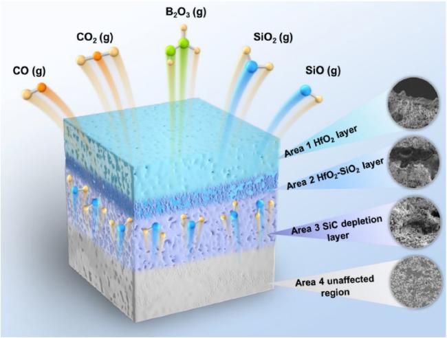
The schematic representation of the ablation mechanism of the HfB2-SiC composites offers a comprehensive understanding of the entire ablation process. Fig. 26 presents a schematic of the ablation behaviors and mechanisms specific to the HfB2-SiC composites. This illustration shows the formation of a dense HfO2-SiO2 oxidation protective layer, where viscous SiO2 integrates into the relatively dense HfO2. At ablation temperatures exceeding 1800 °C and in environments with high oxygen partial pressures, SiO2 and SiC transition from passive to active oxidation. This change leads to rapid evaporation and decomposition (Eqs. (7) and (8)). Therefore, the reduction in SiC creates pores in the originally compact matrix layer, resulting in a region depleted of SiC. Additionally, the oxidation of residual carbon in the HfB2-SiC composites generates CO and CO2 gases (Eqs. (9) and (10)). The outermost layer consists of a relatively dense HfO2, as depicted in Fig. 15. When the ablation temperature of the oxyacetylene torch stabilizes at 2500 °C, this dense HfO2 surface layer, with its lower thermal conductivity, impedes the rate of heat transfer from the ablation surface to the internal material, which effectively insulates the surface heat. It has been observed that under identical evaluation conditions, the HfB2-SiC composites display a unique combination of low density, high-temperature resistance, and extended service life, which endows it an outperforming other thermal protection material in terms of ablation resistance.
UHTCs hold immense potential in high-temperature protection applications. Their oxidation and ablation resistance are critical factors determining their reliability and service life. By conducting in-depth studies on the oxidation behavior and ablation mechanisms of these materials, optimized material systems can be designed to address increasingly harsh operational environments. Current research focuses on developing testing methods that simulate real service conditions and using experimental data to optimize and improve material performance. Future research will aim to enhance the oxidation and ablation resistance of UHTCs, driving their widespread application in hypersonic vehicles and other high-temperature environments.
6 High entropy UHTCs and their composites
With the rapid development of aerospace technology, the requirements for high-temperature structural materials are becoming increasingly stringent. UHTCs have become a research focus in extreme environmental materials due to their extremely high melting point and excellent oxidation resistance. However, traditional UHTC materials such as HfC and ZrC, although having high melting points, are brittle and have poor thermal shock resistance, which limits their practical applications in engineering. In order to overcome these problems, the emerging material of high entropy ultra-high temperature ceramics (HE-UHTCs) has emerged. This section will review the research progress of HE-UHTCs and their composite materials, focusing on their structural characteristics, performance data, and application prospects.
6.1 Concept and characteristics of high entropy UHTCs
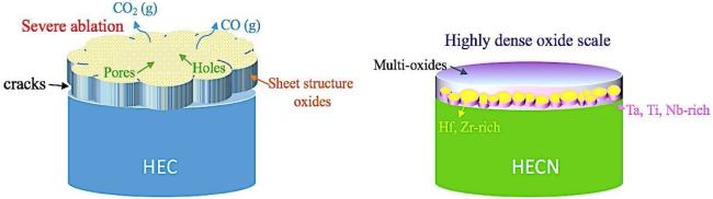
The concept of high-entropy alloys (HEAs) was first introduced in the field of metallic materials, referring to alloys composed of five or more metallic elements in equimolar ratios. Based on this principle, HE-UHTCs are composed of carbides, nitrides, or borides of multiple metallic elements. Compared to traditional UHTCs, HE-UHTCs achieve enhanced thermodynamic stability and mechanical properties by incorporating multiple elements to form complex solid solutions. [163⇓⇓⇓⇓-168]. HE-UHTCs exhibit excellent thermodynamic stability. For instance, using first-principles calculations the Hf-V-Nb-Ta-C system was determined to achieve a melting point as high as 4400 °C, significantly exceeding that of conventional single-phase carbide materials [169]. HE-UHTCs also demonstrate remarkable mechanical properties. Taking the Hf-Ta-Zr-Nb-C system as an example, its Vickers hardness reaches 36 GPa, which is notably higher than that of single-component carbide ceramics [170]. Additionally, studies found that the Ti-Zr-Nb-Hf-Ta HE-UHTC maintains a strength of over 750 MPa at 1800 °C, indicating outstanding mechanical performance at elevated temperatures [171]. Oxidation resistance is a critical indicator for high-temperature structural materials. Sun et al. [172] utilized ten types of transition metal carbide and nitride ceramic powders to prepare high-entropy ceramics, (Ta0.2Hf0.2Zr0.2Ti0.2Nb0.2)C (HEC) and (Ta0.2Hf0.2Zr0.2Ti0.2Nb0.2)C0.8N0.2 (HECN) , via high-energy ball milling and spark plasma sintering, and evaluated its ablation performance at 2500 K. The results showed that the introduction of nitrogen reduced the mass ablation rate and linear ablation rate by 57 ± 1% and 72 ± 1%, respectively. At the ablation center, HECN formed a dense oxide protective layer, effectively preventing oxygen penetration into the ceramic interior. This demonstrates that the incorporation of nitrogen significantly enhances the ceramic's ablation resistance (as shown in Fig. 27). Due to lattice distortion enhancing phonon scattering, the thermal conductivity of HE-UHTCs is generally lower than that of their constituent single materials, thereby exhibiting superior thermal insulation properties [173]. Four types of high-density high-entropy boride ceramics were successfully synthesized by Gild et al. [174], and it was observed that these materials exhibit exceptionally low thermal conductivities, ranging from 12 to 25 W/(m·K), which are approximately one-tenth to one-fifth of the reported values for HfB2 and ZrB2.
6.2 Research progress on high entropy UHTC composite materials
The preparation of high-entropy ceramics primarily relies on powder metallurgy techniques. Therefore, the synthesis of high-entropy ceramic powders becomes particularly significant. Du et al. [175⇓-177] have successfully developed carbide high-entropy ceramic powders through the precursor method. This approach results in powders with lower oxygen content compared to other methods, significantly enhancing the potential applications of HE-UHTCs in coatings and ceramic matrix composites. To further enhance the toughness and thermal shock resistance of HE-UHTCs, researchers have explored combining them with materials such as carbon fibers and silicon carbide fibers to develop HE-UHTCs. The incorporation of toughening phases not only retains the high-temperature stability of HE-UHTCs but also significantly improves the overall performance of the composite materials. Carbon fiber-reinforced HE-UHTCs exhibit significant improvements in mechanical properties. Fang et al [178] fabricated Cf/(Ti0.2Zr0.2Hf0.2Nb0.2Ta0.2)B2-SiC composites using chopped carbon fibers (as shown in Fig. 28), achieving a high density of 97.9% and excellent mechanical performance, including a flexural strength of 411 ± 3 MPa, fracture toughness of 6.15 ± 0.11 MPa·m1/2, and an improved damage tolerance parameter (Dt) from 0.10 m1/2 for HEB-SiC to 0.29 m1/2 for Cf/HEB-SiC. SiC whiskers are another effective choice for toughening high-entropy ceramics. It was shown that SiC whisker-reinforced Ti-Zr-Hf-Nb-Ta-C composites exhibited a fracture toughness of 4.3 ± 0.3 MPa·m1/2, a 43% improvement compared to 3.0 ± 0.2 MPa·m1/2 for pure Ti-Zr-Hf-Nb-Ta-C ceramics. The primary toughening mechanisms include crack deflection, fiber debonding, and fiber pull-out [179].
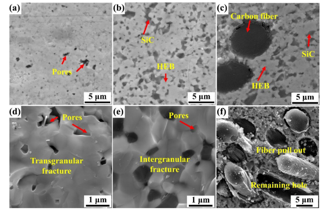
Fig. 28. Polished and fracture surfaces of (a, d) HEB, (b, e) HEB-SiC, and (c, f) Cf-HEB-SiC. Reproduced with permission from Ref. [178], ©The Author(s) 2024. |
Furthermore, to significantly enhance thermal insulation, porous structures were incorporated into high-entropy ceramics, imparting the materials with exceptional mechanical properties and high thermal insulation capabilities, making them ideal candidates for achieving efficient thermal insulation under extreme conditions [180-181]. A 9-cation porous high-entropy diboride ceramic was successfully developed using the ultrafast high-temperature synthesis technique by Wen et al.[182]. These ceramics exhibit outstanding mechanical and thermophysical properties. Their microstructure are characterized by ultrafine pores, high-quality interfacial bonding between nanoscale building blocks, and significant lattice distortion. These factors synergistically contribute to the material's ultra-high compressive strength of approximately 337 MPa at room temperature, despite having a porosity of about 50%, while maintaining an extremely low thermal conductivity of approximately 0.76 W·m⁻¹·K⁻¹. Additionally, the radiation resistance of high-entropy ceramics has been investigated, with the aim of expanding their potential applications in extreme environments such as nuclear energy [183]. Given the high designability of high-entropy alloys, relying solely on experimental means to comprehensively explore their performance progress is slow. Therefore, computational simulations and theoretical prediction techniques are widely adopted to estimate the properties of HE-UHTCs. This strategy facilitates the targeted design and development of novel high-entropy ceramic systems based on specific service environments, thereby precisely meeting application requirements under various extreme conditions [184-185].
HE-UHTCs and their composites demonstrate immense potential in aerospace, hypersonic vehicles, and nuclear energy applications. The high-entropy effect endows HE-UHTCs with exceptional thermal stability, oxidation resistance, mechanical properties and irradiation resistance, particularly in extreme environments [186⇓⇓⇓⇓⇓-192]. Their multi-element solid solution structure effectively addresses the complex physicochemical conditions encountered under such scenarios. However, HE-UHTCs face challenges in practical applications. Firstly, their production costs are relatively high due to the incorporation of multiple metallic elements and the complexity of fabrication processes. Secondly, enhancing the toughness and thermal shock resistance of HE-UHTCs remains a critical focus for future research. Efforts are being made to optimize material properties through approaches such as nanostructure regulation and composite design.
Additionally, the long-term stability and oxidation resistance of HE-UHTCs in high-temperature environments require more rigorous testing to ensure their reliability in practical applications. HE-UHTCs and their composites represent significant research potential in the field of materials science. By leveraging the high-entropy effect, these materials exhibit outstanding performance under extreme conditions such as elevated temperatures. Despite challenges in fabrication costs and engineering applications, ongoing research and technological advancements are expected to enable HE-UHTCs to play an increasingly critical role in extreme environment materials and drive the development of high-temperature structural materials.
7 Application of UHTCs and their composite materials in extreme environments
UHTCs are gaining widespread attention in aerospace, military defense, and energy sectors due to their extremely high melting points, excellent oxidation resistance, and outstanding mechanical strength at elevated temperatures. As performance demands continue to grow, UHTCs are increasingly regarded as one of the core materials for addressing challenges in extreme environments [193]. The following provides an overview of advancements in the application of UHTC composites under extreme conditions, with a focus on their use in aerospace, re-entry vehicles, hypersonic vehicles, and nuclear energy environments, supported by relevant data.
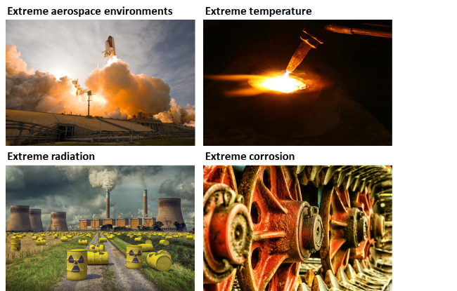
Fig. 29. Materials for applications in extreme environments. All images are from Pixabay. |
7.1 Thermal protection system for re-entry vehicles
Re-entry vehicles experience extreme high temperatures and intense thermal shocks when returning to earth's atmosphere, requiring materials with exceptional high-temperature resistance and thermal shock resistance. Ultra-high-temperature ceramic composites, such as ZrC and HfC-based composites, are preferred materials for thermal protection systems due to their melting points exceeding 3500 °C. Yan [194] fabricated Cf/HfC-SiC composites using PIP. These composites exhibited a thermal conductivity of 21.4 W/(m·K), and under the same ablation conditions, their surface temperature was 2120 °C, which was 440 °C lower than that of low-thermal-conductivity Cf/HfC-SiC composites. The mass ablation rate and linear ablation rate of the high-thermal-conductivity composite were 0.33 ± 0.02 mg/cm2·s and 0.001 ± 0.0001 mm/s, respectively. A protective layer formed by SiO2 and HfO2 provided the composite with excellent ablation resistance and oxidation resistance.
7.2 Thermal protection of hypersonic aircraft
Hypersonic vehicles encounter extremely high dynamic pressure and heat flux during flight, with surface temperatures exceeding 2000 °C. This requires materials not only capable of withstanding high temperatures but also possessing excellent thermal conductivity and ablation resistance. To address this, high-thermal-conductivity carbon fiber-reinforced UHTC composites have been developed. Hu et al. [195] fabricated Cf/HfB2-SiC composites using intermediate-phase pitch-based carbon fiber preforms and a solid-liquid composite process. The composites exhibited remarkable thermal conductivity in the x-direction, with a thermal conductivity of 161.11 W/(m·K) at room temperature, an order of magnitude higher than traditional carbon fiber-reinforced UHTC composites.
7.3 Nuclear energy field
In nuclear reactors, particularly future fast reactors and molten salt reactors, materials must be exposed to high temperatures, intense radiation, and corrosive environments for extended periods. If the materials lack sufficient radiation resistance, they will be prone to internal defects such as dislocations, bubbles, and lattice expansion, leading to performance degradation or even failure [186]. This can compromise the structural stability of reactors and increase the risk of safety accidents. In response to this need, Ultra-high-temperature ceramics, especially ZrC-based materials, are considered important candidates for structural materials in nuclear reactors due to their excellent radiation resistance and high-temperature stability [197-198]. Bao et al [199] irradiated ZrC ceramics with 540 keV He2+ ions at room temperature with a fluence of 1×10¹⁷/cm² and found that the irradiated ZrC ceramics neither amorphous nor exhibited helium-induced cavities, cracks, or extended dislocations. Instead, they maintained structural integrity. Li et al [200] studied the irradiation response of Al2O3-ZrO2-ZrC ceramic composites under 500 keV He ion irradiation at room temperature. The absence of phase transformation and the maximum volume expansion of less than 0.72% after irradiation indicate that the Al2O3-ZrO2-ZrC ceramic composites exhibit better radiation resistance than single-phase ceramics. The excellent radiation resistance of ZrC may originate from its mixed characteristics of covalent, metallic, and ionic properties [201]. In recent years, high-entropy ceramics have also gained attention from researchers for their outstanding properties and have demonstrated superior radiation resistance compared to traditional ultra-high temperature ceramics [202]. Zhang et al [203] studied the helium ion irradiation and helium behavior of ZrC and (Zr0.2Ti0.2Nb0.2Ta0.2W0.2)C at 540 keV. After irradiation, both ZrC and (Zr0.2Ti0.2Nb0.2Ta0.2W0.2)C maintained lattice integrity. However, the irradiation-induced lattice expansion of (Zr0.2Ti0.2Nb0.2Ta0.2W0.2)C was smaller (0.78%) and its thermodynamic stability was higher than that of ZrC (expansion rate of 0.91%). Additionally, the high-entropy effect facilitated favorable structural evolution, including smaller and uniformly distributed helium bubbles without abnormal coarsening or aggregation, as well as shorter and more sparsely distributed dislocations.
UHTCs demonstrate immense application potential in addressing challenges posed by extreme environments. Through continuous optimization of material design, improvements in fabrication techniques, and performance enhancements, these materials are founding expanding applications in aerospace, nuclear energy, and chemical industries. Data indicates that UHTCs not only significantly improve durability and stability under extreme conditions but also reduce maintenance costs and enhance overall system efficiency. Despite facing challenges in practical applications, such as the complexity of fabrication processes and issues related to long-term material stability, advancements in technology and further research are expected to broaden the application prospects of UHTCs in extreme environments, driving rapid development in related industries.
8 Future development directions and challenges of UHTCs
8.1 Diversification of material design and nanostructure regulation
Future material design trends will focus increasingly on diversification and nanoscale structure regulation to further enhance the overall performance of UHTCs. The introduction of multiple elements or compounds to create high-entropy effects or nanocomposite structures can significantly improve the thermodynamic stability and mechanical properties of materials. It has shown that diversified design effectively inhibits grain growth and enhances high-temperature stability.
Additionally, nanoscale structure regulation is another critical direction for future development. Incorporating nanoparticles, nanofibers, or nanoscale layered structures can significantly improve the toughness and thermal shock resistance of composite materials. This nano-enhancement effect arises from toughening mechanisms at the microscopic scale, such as crack blunting, crack deflection, and energy dissipation.
8.2 Innovation and optimization of preparation process
The innovation and optimization of fabrication processes are crucial for the large-scale application of UHTCs. Traditional powder metallurgy methods, such as SPS and HP, can produce high-performance UHTCs in laboratory settings but are constrained by high costs and lengthy production cycles, limiting industrial applications.
Future development will primarily focus on the following areas: additive manufacturing technologies, with their efficient and precise forming capabilities, to achieve densification of complex structures; reaction sintering and chemical vapor infiltration techniques to produce large-scale, high-density UHTCs and optimize interface structures; and mechanical alloying and nano-powder preparation techniques to improve material uniformity and reactivity, facilitating the formation of ultrafine grain structures and enhancing overall performance.
8.3 Active-passive thermal protection
As the speed continues to increase, hypersonic vehicles and re-entry vehicles face extreme thermal loads while traversing the atmosphere. This demands materials with exceptional heat resistance and the capability to provide effective thermal protection under dynamic conditions. The integration of active and passive thermal protection using UHTC composite technologies represents a key development direction to address these challenges.
Active-passive thermal protection combines the advantages of active systems (e.g., cooling mechanisms) and passive systems (e.g., high-temperature-resistant materials) to achieve comprehensive thermal protection. Passive protection is typically provided by UHTC composites, which, with their high melting points and oxidation resistance, can withstand extreme thermal environments. Active protection, on the other hand, employs internal or surface cooling systems, such as microchannel cooling or spray cooling, to further reduce thermal stress and surface temperatures.
However, the practical application of integrated active-passive thermal protection technology faces several challenges. First, the design and integration of cooling systems are complex and must ensure long-term reliability under high-temperature and high-stress conditions. Additionally, optimizing the integration of cooling systems with UHTC composites without compromising the mechanical properties of the materials remains a subject of ongoing research.
8.4 Interface layer and composite structure design
The design of the interface layer is crucial to the overall performance of composites. Future research will place greater emphasis on optimizing the interface layer by incorporating novel interface materials (such as BN and SiC) and multilayer interface structures to enhance the thermal shock resistance and toughness of composites. Furthermore, composite structure design is expected to progress toward greater complexity and refinement, including multi-scale composites and gradient structure designs, to achieve comprehensive performance enhancements.
8.5 Large scale preparation and cost control of UHTCs
Although high-performance UHTCs can already be fabricated in laboratories, their high costs and complex manufacturing processes pose challenges for industrial applications. Future research should focus on developing more cost-effective fabrication methods, such as additive manufacturing and low-temperature sintering technologies, to reduce production costs. Additionally, the development of alternative raw materials to decrease reliance on rare elements will also contribute to cost control.
8.6 Simulation and theoretical prediction of high entropy ceramics
Using computational materials science techniques (such as density functional theory and thermodynamic simulations), the relationship between the microstructure and mechanical properties of high-entropy ceramics can be deeply investigated. By integrating artificial intelligence and machine learning, potential new material systems can be identified through big data screening, thereby accelerating the development process.
8.7 Design and verification in engineering applications
The engineering applications of UHTCs depend not only on their intrinsic properties but also on their performance in complex environments. Therefore, future research should emphasize application validation, including mechanical performance testing under actual operating conditions, as well as high-temperature oxidation and ablation experiments. Additionally, the machinability and assembly processes of these materials are critical factors influencing their application and require further exploration.
UHTCs composites hold great promise for applications in extreme environments. Through diversified design, nanoscale structure regulation, innovative fabrication methods, and performance optimization, the overall properties of UHTCs will be significantly improved. However, challenges remain in terms of material toughness, cost control, and high-temperature stability. Future research should integrate materials science, engineering technology, and application demands to explore UHTCs development from multiple dimensions, driving their widespread use in aerospace, energy, defense, and other fields.
9 Conclusions
This article comprehensively reviews the research progress of UHTCs and their composite materials in extreme environments, focusing on their basic properties, toughening methods, preparation processes, and potential applications in aerospace and other fields. Ultra-high temperature ceramic materials exhibit significant advantages in extreme high-temperature environments due to their excellent high-temperature stability, mechanical strength, and oxidation resistance, making them particularly suitable for thermal protection systems in hypersonic vehicles. However, the inherent brittleness of ultra-high temperature ceramics limits their application under complex stress conditions. Therefore, researchers have significantly improved the toughness and crack resistance of these materials through various methods such as particle toughening, soft phase toughening, short fiber toughening, and continuous fiber toughening.
In terms of preparation technology, this article reviews various methods from traditional hot pressing sintering to advanced additive manufacturing technology, and explores the advantages and disadvantages of each method and their impact on material properties. Especially the innovative "solid-liquid" combination process, which combines solid-phase vibration grouting with liquid-phase ultra-high pressure impregnation, has achieved efficient densification and performance improvement of ultra-high temperature ceramic composite materials, providing new ideas for solving the problem of material densification. In addition, technologies such as reactive melt infiltration and precursor impregnation cracking have also demonstrated great potential in the preparation of fiber-reinforced UHTC composites.
Although these technologies have significantly improved the performance of ultra-high temperature ceramic materials, in practical applications, the long-term stability of materials at high temperatures, interface bonding strength, and the preparation of large-sized components still face many challenges. Future research should focus on the development of new material systems, optimization of process parameters, and long-term performance verification of materials under extreme conditions. In addition, through interdisciplinary collaboration, further enhancing the comprehensive performance of UHTCs and their composite materials will lay a solid foundation for meeting the demanding requirements of hypersonic aircraft and other extreme environments.
Acknowledgements
This work was supported by Major Program of National Natural Science Foundation of China (No. 52293372), Key Program of National Natural Science Foundation of China (No. 52032003), National Natural Science Foundation of China (No. 52372080).
Fund
Declaration of competing interest
The authors have no competing interests to declare that are relevant to the content of this article.