×
模态框(Modal)标题
在这里添加一些文本
Close
Close
Submit
Cancel
Confirm
×
模态框(Modal)标题
×
Submit
Search
Toggle navigation
Home
About Journal
Journal Information
Editorial Board
Awards
Journal Metrics
Contact
Journal Online
Just Accepted
Current Issue
Highlights
Archive
Most Read
Most Download
Most Cited
Guide for Authors
Subscribe
EM in KeAi
Figure/Table detail
Sensing-Actuating Performance of Flexible Piezoelectric Composites by Component Optimization
Yanheng Guo, Weixuan Zhang, Kecheng Li, Di Wu, Tao Liu, Wenfeng Zhang, Yishou Wang
Extreme Materials
, DOI:
10.1016/j.exm.2025.05.001
Fig. 16.
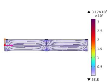
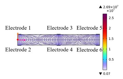
Effect of electrode spacing on the electric field distribution region for D31-FPC
Other figure/table from this article
Fig. 1.
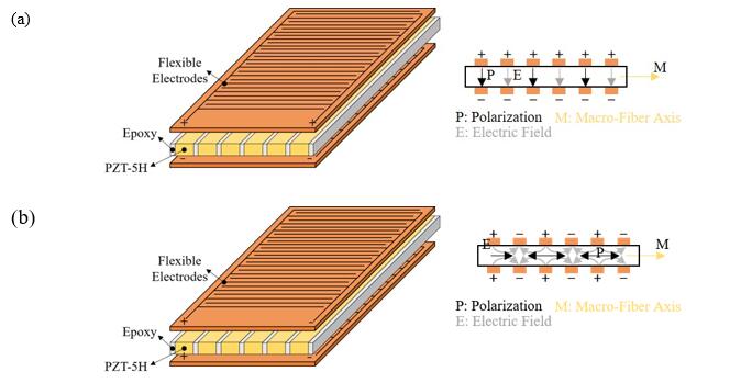
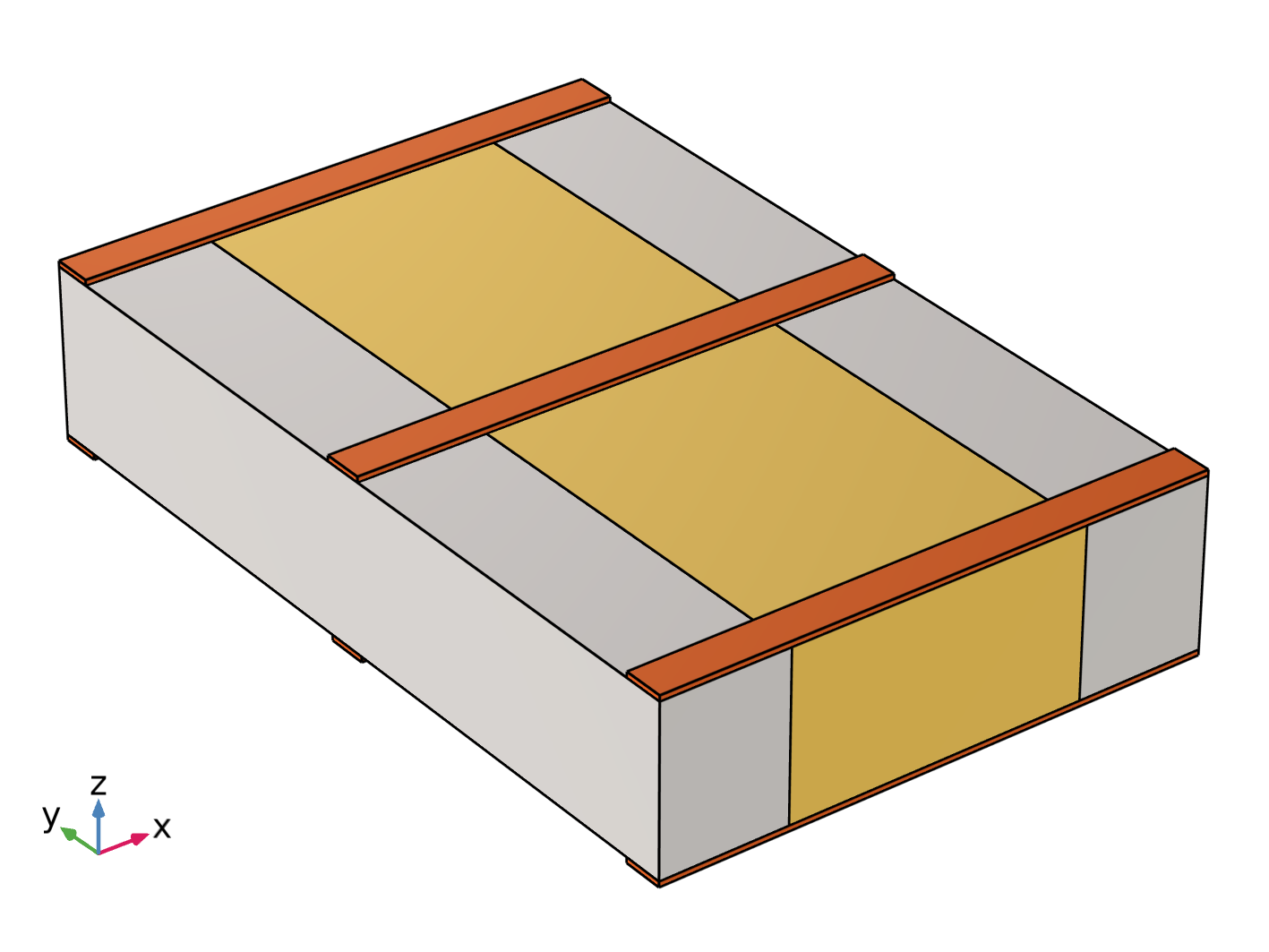
A schematic diagram of an FPC structure. (a) D31-FPC. (b) D33-FPC
Fig. 2.
RVE model of FPC. (a) RVE model of D33-FPC. (b) RVE model of D31-FPC
Table 1
Geometrical parameters of RVE model components
Table 2
Material properties of RVE components
Fig. 3.
(a)RVE model. (b) mesh scheme
Table 3
RVE model parameters for different PZT volume fractions
Fig. 4.
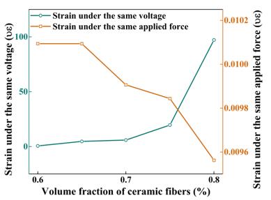
Variation of strain with fiber volume fraction for D33-RVE under the same electromechanical conditions
Fig. 5.
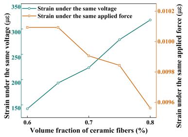
Variation of strain with fiber volume fraction for D31-RVE under the same electromechanical conditions
Fig. 6.
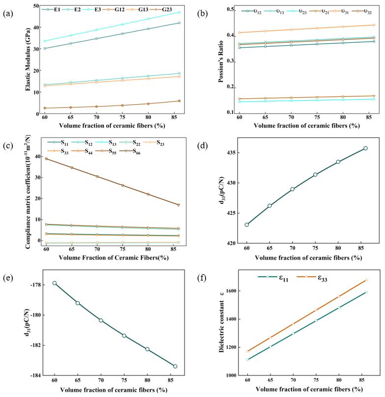
(a) Effect of ceramic fiber volume fraction on the elastic modulus of the piezoelectric active layer. (b) Effect of ceramic fiber volume fraction on the Possion’s Ratio of the piezoelectric active layer. (c) Effect of ceramic fiber volume fraction on the compliance of the piezoelectric active layer. (d) Effect of ceramic fiber volume fraction on the piezoelectric constant d33 of the piezoelectric active layer. (e) Effect of ceramic fiber volume fraction on the piezoelectric constant d31 of the piezoelectric active layer. (f) Effect of ceramic fiber volume fraction on the Dielectric Constant of the piezoelectric active layer.
Fig. 7.
Electric field distribution in the yOz plane of the RVE model for D33-FPC
Fig. 8.
Electric field distribution in the yOz plane of the RVE model for D31-FPC
Fig. 9.
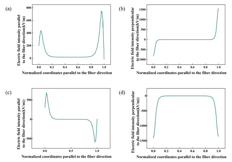
(a) Electric field intensity parallel to the fiber direction for D33-Type FPC; (b) Electric field intensity perpendicular to the fiber direction for D33-Type FPC; (c) Electric field intensity parallel to the fiber direction for D31-Type FPC; (d) Electric field intensity perpendicular to the fiber direction for D31-Type FPC
Fig. 10.
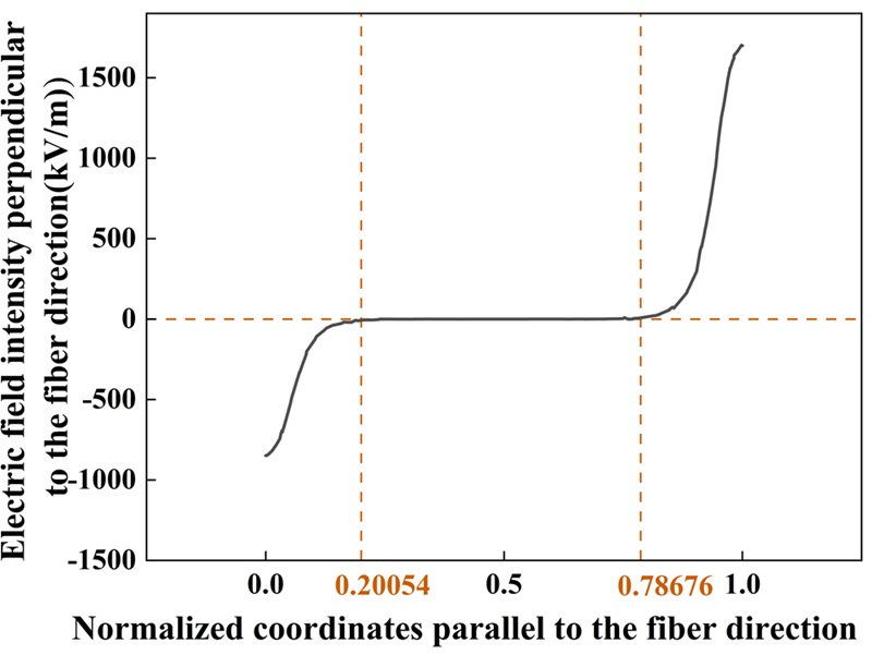
Distribution of the electric field component perpendicular to the fiber direction between electrodes for D33-type FPC (the horizontal axis representing the normalized coordinate parallel to the electric field direction, i.e., the ratio of the distance from the observation point to the electrode centerline to the electrode spacing)
Table 4
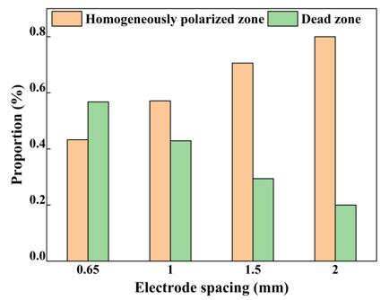
Effect of electrode spacing on the proportions of homogeneously polarization zone and dead zone in D33-FPC
Fig. 11.
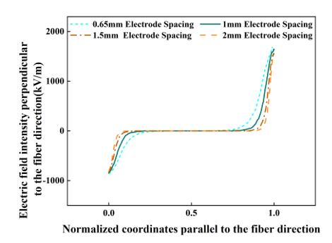
Effect of electrode spacing on the electric field intensity perpendicular to the fiber direction for D33- FPC
Fig. 12.
Effect of electrode spacing on the electric field distribution region for D33-FPC
Fig. 13.
Effect of electrode spacing on the electric field intensity parallel to the fiber direction for D33-FPC
Fig. 14.
Variation trend of the applied electric field intensity and effective electric field area ratio with electrode spacing in D33-FPC
Table 5
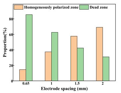
Effect of electrode spacing on the proportions of homogeneously polarization zone and dead zone in D31-FPC
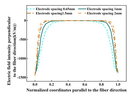
Fig. 15.
Effect of electrode spacing on the electric field distribution perpendicular to the fiber direction for D31-FPC
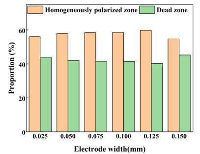
Table 6
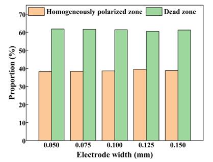
Effect of electrode width on the proportions of homogeneously polarization zone and dead zone in D33-FPC
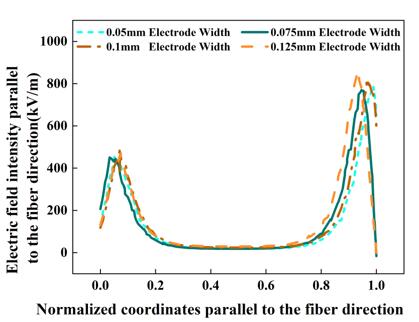
Fig. 17.
Effect of electrode width on the electric field intensity parallel to the fiber direction for D33-Type FPC
Fig. 18.
Effect of electrode width on the electric field distribution region for D33-Type FPC
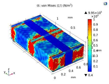
Fig. 19.
Stress distribution of the RVE model of D33-FPC under 400V voltage
Fig. 20.
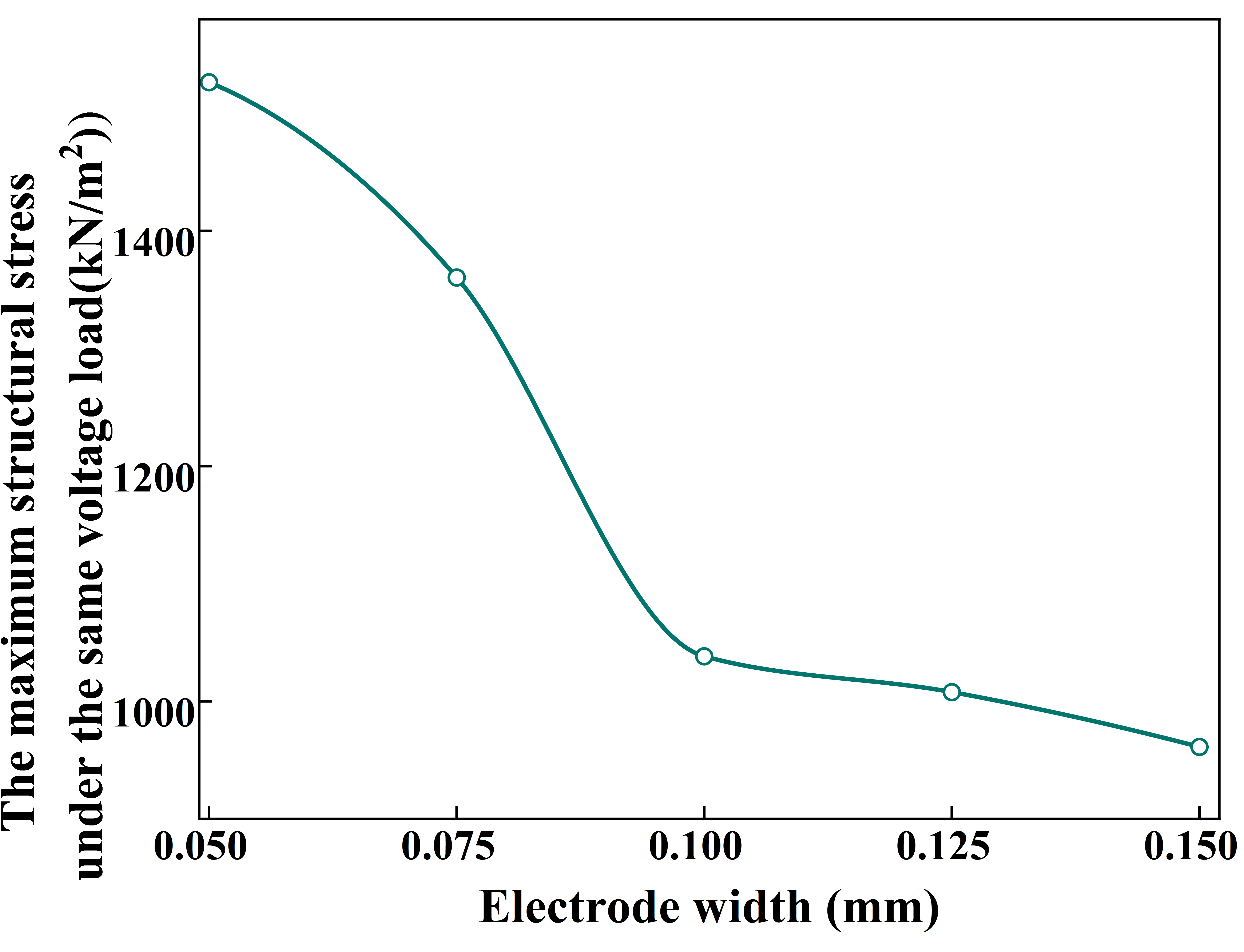
Effect of electrode width on the maximum stress in D33-FPC
Table 7
Effect of Electrode Width on The Proportions of Homogeneously Polarization Zone and Dead Zone in D31-FPC
Fig. 21.
Effect of electrode width on the electric field distribution perpendicular to the fiber direction for D31-FPC
Fig. 22.
Effect of electrode width on the electric field distribution region for D31-FPC
Fig. 23.
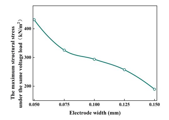
Effect of electrode width on the maximum stress in D31-FPC